


Current to voltage converter proofing
#current-to-voltage converter
#op-amp
#schematic
#ground connection
#circuit design
#signal conversion
#feedback resistor
#precision
#electrical engineering
#circuit analysis

Description: At a T connection, the connections are clear, but at a cross, the connections are not clear, especially if there are no junction dots elsewhere in the schematic. It appears that the bottom of the I and the right side of R2 are intended to be connected to ground, but the schematic indicates otherwise. Attention to detail is crucial. There is a deduction for sloppiness and neglecting standard conventions. Further, the origin of the schematic is irrelevant; the individual who posted it holds responsibility for its clarity. If the cross at the bottom is a no-connection point, it alters the nature of the issue entirely.
The schematic in question presents a T connection that is straightforward, allowing for easy interpretation of the connections. However, the cross connection introduces ambiguity, which can lead to misinterpretation of the circuit's functionality. In standard electronic schematics, junction dots are critical for indicating where connections are made. Their absence at the cross connection can lead to confusion regarding whether the components are intended to be connected or are simply crossing without any electrical interaction.
In this specific case, the mention of the bottom of the I and the right side of R2 suggests that these points are meant to be grounded. Grounding is a common practice in electronic circuits, as it provides a reference point for voltage levels and helps in stabilizing the circuit. If the schematic indicates otherwise, it raises concerns about the accuracy of the design.
Attention to detail is imperative in circuit design, as any oversight can result in functional issues or even damage to components. The criticism regarding sloppiness highlights the importance of adhering to standard conventions in schematic representation. This includes ensuring that all connections are clear and that the schematic accurately reflects the intended design.
The discussion surrounding the origin of the schematic emphasizes the responsibility of the individual who presents the circuit. Regardless of the source, clarity and adherence to conventions must be maintained to ensure that the schematic can be easily understood and accurately implemented. If the cross at the bottom is indeed a no-connection point, it fundamentally changes the interpretation of the circuit, necessitating a thorough review and correction of the schematic to prevent any potential issues in practical applications.At a T connection, it`s clear, but at a cross it`s otherwise not clear, especially if there are no junction dots elsewhere as in your schematic. It looks like the bottom of Is and the right side of R2 are supposed to be connected to ground, but your schematic says otherwise.
Attention to detail matters. -1 for sloppiness and thinking you are above the standard conventions. I guess you should tell that to the publisher; it looks like it`s from a textbook. (In which case all schematics in the book will be like that :-) stevenvh Aug 28 `12 at 13:10 @stevenvh: No, it`s not my issue where the OP got the schematic from. I don`t care if he drew it himself on a napkin, used schematic software himself, or copied it from elsewhere.
He is the one that posted it here, so he has the responsibility for it. There is lots of crap on the internet. It is in no way acceptable to post crap just because you saw it elsewhere. Olin Lathrop Aug 28 `12 at 22:50 I agree with Olin Lathrop. If the cross at the bottom is no connection then the problem becomes a completely different one Federico Russo Jul 29 `13 at 13:19
The schematic in question presents a T connection that is straightforward, allowing for easy interpretation of the connections. However, the cross connection introduces ambiguity, which can lead to misinterpretation of the circuit's functionality. In standard electronic schematics, junction dots are critical for indicating where connections are made. Their absence at the cross connection can lead to confusion regarding whether the components are intended to be connected or are simply crossing without any electrical interaction.
In this specific case, the mention of the bottom of the I and the right side of R2 suggests that these points are meant to be grounded. Grounding is a common practice in electronic circuits, as it provides a reference point for voltage levels and helps in stabilizing the circuit. If the schematic indicates otherwise, it raises concerns about the accuracy of the design.
Attention to detail is imperative in circuit design, as any oversight can result in functional issues or even damage to components. The criticism regarding sloppiness highlights the importance of adhering to standard conventions in schematic representation. This includes ensuring that all connections are clear and that the schematic accurately reflects the intended design.
The discussion surrounding the origin of the schematic emphasizes the responsibility of the individual who presents the circuit. Regardless of the source, clarity and adherence to conventions must be maintained to ensure that the schematic can be easily understood and accurately implemented. If the cross at the bottom is indeed a no-connection point, it fundamentally changes the interpretation of the circuit, necessitating a thorough review and correction of the schematic to prevent any potential issues in practical applications.At a T connection, it`s clear, but at a cross it`s otherwise not clear, especially if there are no junction dots elsewhere as in your schematic. It looks like the bottom of Is and the right side of R2 are supposed to be connected to ground, but your schematic says otherwise.
Attention to detail matters. -1 for sloppiness and thinking you are above the standard conventions. I guess you should tell that to the publisher; it looks like it`s from a textbook. (In which case all schematics in the book will be like that :-) stevenvh Aug 28 `12 at 13:10 @stevenvh: No, it`s not my issue where the OP got the schematic from. I don`t care if he drew it himself on a napkin, used schematic software himself, or copied it from elsewhere.
He is the one that posted it here, so he has the responsibility for it. There is lots of crap on the internet. It is in no way acceptable to post crap just because you saw it elsewhere. Olin Lathrop Aug 28 `12 at 22:50 I agree with Olin Lathrop. If the cross at the bottom is no connection then the problem becomes a completely different one Federico Russo Jul 29 `13 at 13:19

How to Read a Schematic
Electronic circuits are presented in schematic form. A schematic is essentially a map that illustrates the path of current through various components. Each component is represented by a symbol, typically accompanied by a label or a value, or both. The...
Precision Amplifiers
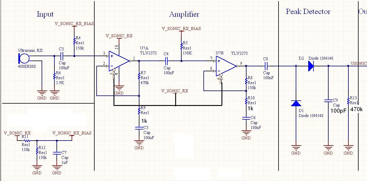
It has been mentioned that the operational amplifier (op amp) in the second stage may be damaged. Confirmation is requested by testing the op amp in a buffer configuration or any simple configuration. This test is necessary to ascertain whether...
Window-detector
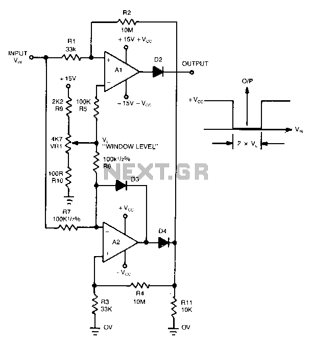
This novel window detector utilizes only two operational amplifiers. The width of the window can be adjusted using a 4.7 kΩ potentiometer.
The described window detector circuit employs two operational amplifiers (op-amps) to create a functional and efficient signal conditioning system....
op amp Could someone help me understand this simple circuit
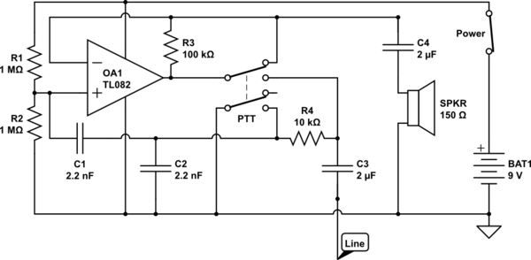
The circuit operates in receive mode, with the Push-To-Talk (PTT) switch enabling transmit mode. The speaker functions as both a microphone and a speaker. Most systems observed utilize a rocking armature transducer for the speaker. There is no base station...

Single Input to Differential Input Adapter for Digital Voltmeter
In some cases, a differential input is needed for voltage measurement. By using a single operational amplifier, it is possible to construct an adapter that provides a floating voltage reference.
To achieve a differential input for voltage measurement using an operational...
Op Amp Power Driver
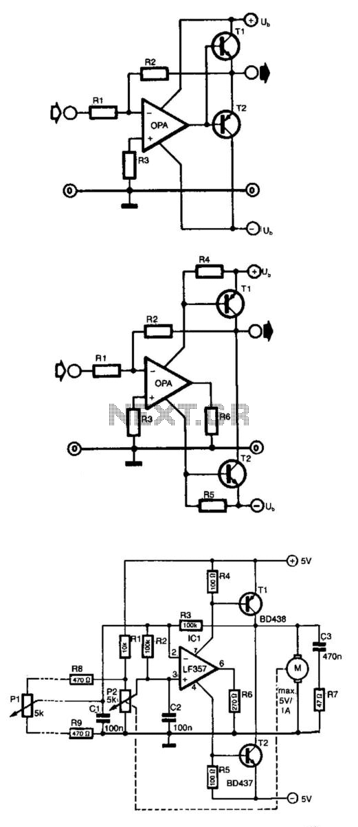
Frequently, the output current of an operational amplifier is inadequate for applications such as driving a small motor or loudspeaker. This issue is typically resolved by adding an emitter follower to the circuit. However, this configuration does not allow the...
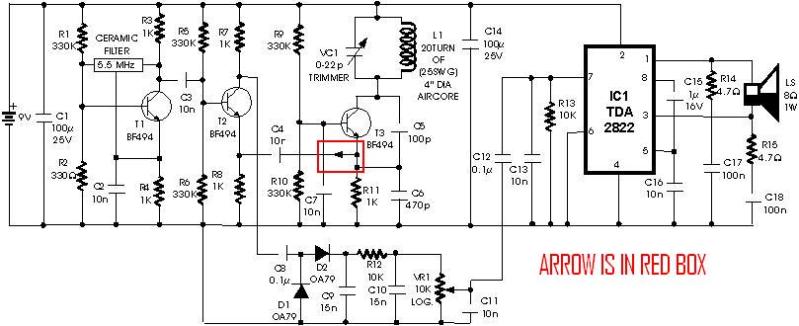
metal detector project circuit
A schematic diagram for a metal detector has been found. The project does not need to be original and can be sourced from the internet. There are several questions regarding this schematic. One query pertains to a small arrow connected...

The Universal Linear Component
Operational amplifiers are the simplest and most effective means of executing a variety of linear functions, ranging from basic amplification to intricate analog computations.
Operational amplifiers (op-amps) are versatile components widely utilized in electronic circuits for various applications. These devices can...
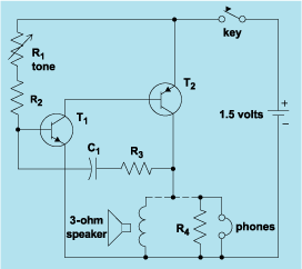
schematic diagram graphic arts
Schematic diagram. A presentation of the element-by-element relationship of all parts of a system.
A schematic diagram serves as a crucial tool in electronic design and engineering, representing the interconnections and relationships between various components within a system. It provides a...