


Full-Wave Rectifier (To 10 Mhz)
#full-wave rectifier
#op-amp
#transistor array
#CA3450
#CA3227
#high frequency
#signal processing
#rectification
#10 MHz

Description: This circuit employs two CA3450 operational amplifiers and a CA3227 transistor array to achieve accurate full-wave rectification of signals up to 10 MHz. Two of the CA3227 transistors are responsible for driving the output, while the other two are integrated into the feedback circuits. Additionally, two transistors function as clamping diodes to limit the negative-going signals from each amplifier, ensuring both amplifiers remain active during the end cycle. The maximum output is dictated by a slew rate of 300 V/µs at the highest frequencies.
The circuit utilizes the CA3450 op-amps, known for their high-speed performance and low distortion, making them suitable for processing high-frequency signals. The full-wave rectification process is achieved by configuring the op-amps in a differential arrangement, allowing them to respond to both the positive and negative halves of the input waveform. The CA3227 transistor array complements this setup by providing additional drive capability and feedback stabilization.
In the feedback loops, the transistors play a crucial role in maintaining linearity and stability within the circuit. By incorporating feedback, the design minimizes distortion and enhances the fidelity of the rectified output. The clamping diodes, formed by the CA3227 transistors, are essential for protecting the op-amps from negative voltage excursions, which could potentially lead to clipping or damage.
The slew rate of 300 V/µs indicates that the circuit can handle rapid changes in the input signal without significant lag, making it ideal for high-frequency applications. This characteristic is particularly important when dealing with signals near the upper limit of 10 MHz, where transient response and fidelity are critical.
Overall, this circuit design effectively combines high-performance components to achieve reliable full-wave rectification in applications requiring precision and speed, such as RF signal processing and high-frequency signal conditioning. Using two CA3450 op amps and a CA3227 transistor array, this circuit will accurately full-wave rectify sign als to 10 MHz. Two of the CA3227 transistors drive the output, two are in the feedback circuits. Two transistors serve as clamping diodes, limit the negative-going signals of each amplifier, and keep both amplifiers active during the end cycle. The maximum output is determined by the slew rate of 300 V//xs at highest frequencies.
The circuit utilizes the CA3450 op-amps, known for their high-speed performance and low distortion, making them suitable for processing high-frequency signals. The full-wave rectification process is achieved by configuring the op-amps in a differential arrangement, allowing them to respond to both the positive and negative halves of the input waveform. The CA3227 transistor array complements this setup by providing additional drive capability and feedback stabilization.
In the feedback loops, the transistors play a crucial role in maintaining linearity and stability within the circuit. By incorporating feedback, the design minimizes distortion and enhances the fidelity of the rectified output. The clamping diodes, formed by the CA3227 transistors, are essential for protecting the op-amps from negative voltage excursions, which could potentially lead to clipping or damage.
The slew rate of 300 V/µs indicates that the circuit can handle rapid changes in the input signal without significant lag, making it ideal for high-frequency applications. This characteristic is particularly important when dealing with signals near the upper limit of 10 MHz, where transient response and fidelity are critical.
Overall, this circuit design effectively combines high-performance components to achieve reliable full-wave rectification in applications requiring precision and speed, such as RF signal processing and high-frequency signal conditioning. Using two CA3450 op amps and a CA3227 transistor array, this circuit will accurately full-wave rectify sign als to 10 MHz. Two of the CA3227 transistors drive the output, two are in the feedback circuits. Two transistors serve as clamping diodes, limit the negative-going signals of each amplifier, and keep both amplifiers active during the end cycle. The maximum output is determined by the slew rate of 300 V//xs at highest frequencies.

Simple DC to 20 MHz Driver
The output cable from my 20 MHz function/sweep generator dangled over the side of the workbench, the alligator clip hovering over the floor. Deeply engrossed in a project, I moved the power strip on the floor a little closer so...
Overload Indicator Circuit
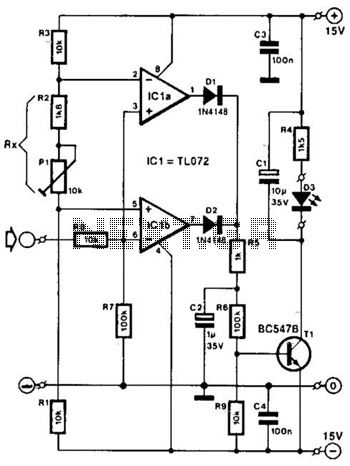
Two operational amplifiers are utilized as comparators to signal an excessive magnitude of an audio frequency (AF) signal, regardless of whether the signal is positive, negative, or asymmetrical. A reference voltage is established for both operational amplifiers using a potentiometer...

High frequency signal generator
A tapped-coil Colpitts oscillator is utilized at Q1 to deliver four tuning ranges: 1.7 to 3.131 MHz, 3.0 to 5.6 MHz, 5.0 to 12 MHz, and 11.5 to 31 MHz. A Zener diode (D2) is incorporated at Q1 to reduce...
Guitar Control
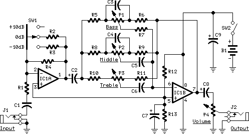
The IC1A operational amplifier is configured as an inverting amplifier, with its gain determined by a three-way switch that connects different resistor values in parallel to R4. Following this input stage is an active three-band tone control circuit, designed to...

Compound Op Amp Vco Driver
This circuit produces a 5 to 25 V output to drive a voltage-controlled oscillator (VCO) from a standard ±15 V supply system. Resistor R7 and capacitor C1 provide frequency compensation. Transistors Q1 through Q3 form an inverting amplifier with a...
Differentiator Op Amp Circuit
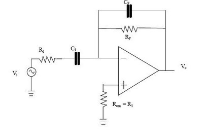
The differentiator circuit is an application circuit derived from mathematical principles influenced by capacitor behavior. The circuit, as illustrated in the accompanying image, is a simple differentiator configuration. To derive the differentiator formula, the following sequence is used: Ic =...

Voltage-Controlled Current Source Uses Two Op Amps
Author Mazi Hosseini describes a simple, low-cost voltage-controlled current source using two operational amplifiers that provides a good range of current and maximum load.
The circuit described by Mazi Hosseini utilizes two operational amplifiers (op-amps) to create a voltage-controlled current source,...

Single Capacitor Powers Audio Mixer
Micropower and low-voltage operational amplifiers enable the construction of high-performance analog signal processors that do not require batteries or wall transformers. Instead, a capacitor can serve as the power source. The circuit illustrated in Figure 1 depicts an analog mixer...

10Mhz coaxial line driver
The circuit is ideal for high-frequency line driving systems that necessitate a wide power bandwidth at elevated output current levels. The integrated circuit used is HA2530. The bandwidth of the circuit is constrained solely by the single pole response of...