


LM359 1MHz Balanced Line Driver
#LM359
#balanced line driver
#differential input
#signal transmission
#1MHz
#audio signal
#noise rejection
#professional audio
#line level
#impedance matching

Balanced signals consist of two lines that have opposite phases and should be received with a differential input receiver. Balanced signals are employed in many applications.
Balanced signals are primarily used in audio and communication systems to minimize noise and interference. They are characterized by sending an identical signal on two conductors, with one conductor carrying the signal in its original phase and the other carrying it in an inverted phase. This configuration allows for the cancellation of any noise that may be induced equally on both lines during transmission.
In a typical balanced signal circuit, the differential input receiver is designed to detect the voltage difference between the two lines. This is crucial because it enhances the immunity to electromagnetic interference (EMI) and radio frequency interference (RFI), which are common in environments where electronic signals are transmitted. The differential receiver amplifies only the difference between the two signals, effectively rejecting any common-mode noise that may have been picked up along the transmission path.
Balanced signal circuits often utilize twisted pair cables, where the two conductors are twisted together to further enhance noise cancellation. This twisting helps to ensure that any external noise affects both conductors equally, allowing the differential receiver to negate this noise.
In practical applications, balanced signals are commonly used in professional audio equipment, such as microphones, mixing consoles, and amplifiers, as well as in data communication systems like Ethernet, where signal integrity is paramount. The implementation of balanced signaling techniques significantly improves the performance and reliability of electronic systems in noisy environments.Balanced signal consist of two lines that have opposite phases, and should be received with differential input receiver. Balanced signal is employed in many..
Balanced signals are primarily used in audio and communication systems to minimize noise and interference. They are characterized by sending an identical signal on two conductors, with one conductor carrying the signal in its original phase and the other carrying it in an inverted phase. This configuration allows for the cancellation of any noise that may be induced equally on both lines during transmission.
In a typical balanced signal circuit, the differential input receiver is designed to detect the voltage difference between the two lines. This is crucial because it enhances the immunity to electromagnetic interference (EMI) and radio frequency interference (RFI), which are common in environments where electronic signals are transmitted. The differential receiver amplifies only the difference between the two signals, effectively rejecting any common-mode noise that may have been picked up along the transmission path.
Balanced signal circuits often utilize twisted pair cables, where the two conductors are twisted together to further enhance noise cancellation. This twisting helps to ensure that any external noise affects both conductors equally, allowing the differential receiver to negate this noise.
In practical applications, balanced signals are commonly used in professional audio equipment, such as microphones, mixing consoles, and amplifiers, as well as in data communication systems like Ethernet, where signal integrity is paramount. The implementation of balanced signaling techniques significantly improves the performance and reliability of electronic systems in noisy environments.Balanced signal consist of two lines that have opposite phases, and should be received with differential input receiver. Balanced signal is employed in many..

No linear feedback amplifier circuit a
The circuit features a differential input stage that implements differential voltage amplification, forced differential voltage amplification, and a complementary push-pull amplifier output. It includes a bias circuit, a distortion servo circuit, and a protection circuit. The input preamplifier stage is...

Simple quality-oriented PA 02
The differential input stage utilizes the integrated differential transistors 2SC1583 and 2SA798, with the amplified signal directed to the power amplifier tubes VT5 and VT6. The performance of the charge directly influences the overall performance of the power amplifier circuit....

rf Can I merge two impedance matching circuits
Place the transceiver and the chip antenna very close together, eliminating the need for a 50-ohm transmission line. If this is the case, can the two matching circuits be merged into one to reduce the component count?
To create an efficient...
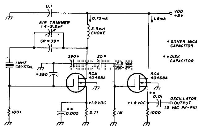
1Mhz fet crystal oscillator
This stable oscillator circuit exhibits less than a 1 Hz frequency change over a VDD range of 3 to 9 volts. Stability is attributed to the use of MOSFET devices and stable capacitors.
The described oscillator circuit is designed to maintain...
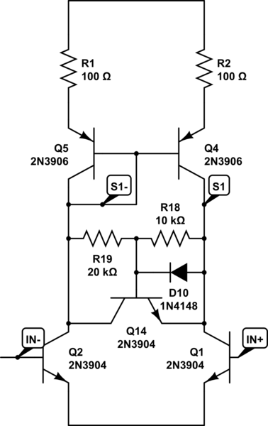
amplifier How to improve nasty form clipping behavior in differential input stage
The amplifier in the following schematic, when simulated, demonstrates the ability to effectively amplify a signal with an amplitude of 0.1V to 10V. However, when subjected to a larger input signal, the performance deteriorates significantly during the positive half cycle,...

1Mhz-pierce-oscillators
The circuit is an inverter configured as a linear amplifier. By incorporating a crystal and capacitors into the feedback path, the amplifier is transformed into an oscillator, enabling it to oscillate at or near the crystal's resonant frequency. Trimmer capacitor...
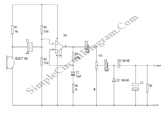
Audio Signal Strength Detector/Converter
Below is the schematic diagram of an audio input module. This module is capable of producing a DC output voltage that is proportional to the amplitude of the input signal.
The audio input module typically consists of several key components that...

1MHz PIERCE OSCILLATORS
A simple network design is a key feature of the Pierce circuit, as illustrated by these 1-MHz oscillators. Operating the crystal slightly above resonance requires only one high-gain transistor stage. Operating it exactly at series resonance requires an additional RC...

DC biasing audio signal
The audio source will be a line-level audio signal ranging from -2V to +2V AC, which will be passed through a 220µF coupling capacitor followed by a two-pole low-pass filter (RC). The signal will be processed by an Analog-to-Digital Converter...