


non inverting opamp butterworth filter
#opamp
#filter
#non-inverting
#Butterworth
#single supply
#signal processing
#analog circuit
#voltage range
#amplification
#electronics

Description: The inquiry pertains to whether a specific circuit will invert the input signal. The operational amplifier (op-amp) is single-supplied with a voltage of 5V, and the input signal varies between 0V and 5V. The question arises regarding the output voltage when the signal is inverted, with the assumption that inverting a positive signal results in a negative one. However, since the op-amp cannot output negative voltages, it is presumed that the output will be 0V. Additionally, if the circuit is indeed inverting, guidance is sought on converting it to a non-inverting configuration. The input signal source possesses a high impedance of approximately 560k ohms, originating from a resistive voltage divider, leading to the suggestion of incorporating a buffer at the input stage of the amplifier.
In this circuit analysis, the operational amplifier is configured with a single supply of 5V, which limits the output voltage range to between 0V and 5V. When an input signal that varies between 0V and 5V is fed into an inverting op-amp configuration, the output voltage will be inverted. For instance, if the input voltage is at its maximum (5V), the theoretical output would be negative, which the op-amp cannot produce due to its power supply constraints. Instead, the output will saturate at 0V, effectively clipping the signal.
To convert this inverting configuration to a non-inverting one, the feedback and input connections need to be rearranged. In a non-inverting op-amp configuration, the input signal is applied directly to the non-inverting terminal, while the inverting terminal is connected to the output through a feedback resistor network. This configuration allows the op-amp to amplify the input signal without inversion, providing a positive output that corresponds to the input signal, scaled by the gain determined by the resistor values in the feedback loop.
Given the high input impedance from the source (560k ohms), it is prudent to implement a buffer (voltage follower) at the input stage of the amplifier. This buffer serves to isolate the high-impedance signal source from the op-amp, preventing loading effects that could distort the input signal. The buffer will provide a low output impedance, allowing it to drive the op-amp input effectively while maintaining the integrity of the input signal.
In summary, the configuration of the op-amp and the input stage must be carefully designed to ensure proper signal processing, with considerations for both the inversion characteristics and the impedance matching to avoid signal degradation.I would like to learn if this circuit will invert the input signal or not. The opamp is single supplied, and supply voltage is 5V. The input signal is varying between 0V and 5V. What happens the the output voltage if the signal is inverted I think, if you invert a positive signal you obtain a negative one, and since the opamp cannot give negative output, it will simply give 0V, am I right If this circuit is inverting, how can I convert it to a non-inverting one There are only two opamps available in the circuit. Source of the input signal has high impedance (around 560k ©, arrives from a resistive voltage divider), so I feel like I must have a buffer at the input stage of the amplifier.
In this circuit analysis, the operational amplifier is configured with a single supply of 5V, which limits the output voltage range to between 0V and 5V. When an input signal that varies between 0V and 5V is fed into an inverting op-amp configuration, the output voltage will be inverted. For instance, if the input voltage is at its maximum (5V), the theoretical output would be negative, which the op-amp cannot produce due to its power supply constraints. Instead, the output will saturate at 0V, effectively clipping the signal.
To convert this inverting configuration to a non-inverting one, the feedback and input connections need to be rearranged. In a non-inverting op-amp configuration, the input signal is applied directly to the non-inverting terminal, while the inverting terminal is connected to the output through a feedback resistor network. This configuration allows the op-amp to amplify the input signal without inversion, providing a positive output that corresponds to the input signal, scaled by the gain determined by the resistor values in the feedback loop.
Given the high input impedance from the source (560k ohms), it is prudent to implement a buffer (voltage follower) at the input stage of the amplifier. This buffer serves to isolate the high-impedance signal source from the op-amp, preventing loading effects that could distort the input signal. The buffer will provide a low output impedance, allowing it to drive the op-amp input effectively while maintaining the integrity of the input signal.
In summary, the configuration of the op-amp and the input stage must be carefully designed to ensure proper signal processing, with considerations for both the inversion characteristics and the impedance matching to avoid signal degradation.I would like to learn if this circuit will invert the input signal or not. The opamp is single supplied, and supply voltage is 5V. The input signal is varying between 0V and 5V. What happens the the output voltage if the signal is inverted I think, if you invert a positive signal you obtain a negative one, and since the opamp cannot give negative output, it will simply give 0V, am I right If this circuit is inverting, how can I convert it to a non-inverting one There are only two opamps available in the circuit. Source of the input signal has high impedance (around 560k ©, arrives from a resistive voltage divider), so I feel like I must have a buffer at the input stage of the amplifier.

Opamp VHF FM Transmitter
Integrated circuits (ICs) that were previously too costly for hobbyists are now more affordably priced. An example is the AD8099 from Analog Devices, which is available for only a few pounds. The AD8099 is a very fast operational amplifier (op-amp)...
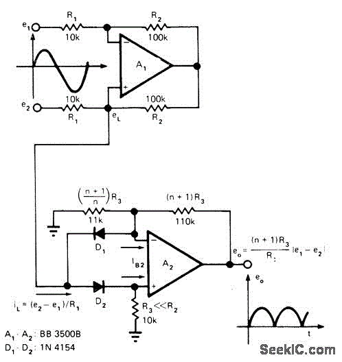
DIFFERENTIAL AC SIGNALS
Precision full-wave rectification of differential voltage is achieved by converting voltage to current for rectification and then reconverting to output voltage. One operational amplifier functions as a voltage-to-current converter, while the other serves as a current-to-current rectifier. This circuit is...

FLOW METER
A simple operational amplifier (op-amp) circuit combined with a transistor creates a reliable hot-wire anemometer for measuring the flow of gases or liquids. Resistor R2 is heated above ambient temperature within a Wheatstone bridge configuration that includes an overheat resistor,...

nescaf
The NEScaf filter is designed to offer greater flexibility than previous filters for QRP (low-power) radio rigs. It features two panel-mounted controls: a single center-detent potentiometer that adjusts the center frequency of the filter's bandpass (settable between approximately 415 Hz...

Stylus sand acoustic filter circuit diagrams
The circuit provides a passband gain of 1 with a corner frequency of 10 kHz, designed to eliminate high-frequency noise such as hiss, ticking, and popping sounds.
This circuit operates as a low-pass filter, effectively attenuating frequencies above the specified corner...

SIX RANGE LIGHT METER
The circuit involves the switching of feedback resistors for an operational amplifier (op-amp) that is driven by a Radio Shack 276-115 selenium solar cell, resulting in a multirange linear light meter. A 1000-megohm resistor is utilized for the highest sensitivity,...

OPTICALLY COUPLED V F
The input voltage range of 0-10 V is converted to a proportional frequency at the output of an optoisolator using the RM4151 converter. This converter is paired with the RC3403A quad op-amp, which serves multiple functions including inverter, integrator, regulator,...

Antialiasing And Sync-Compensation Filter
Two dual-biquad filter chips and some external components form a multipurpose filter to reconstruct D/A converter signals. Connected to a converter's output, the filter provides antialiasing, reduces the D/A converter's quantization noise, and compensates for the "sync" function (attenuation). The...

Interpolating Scanner Circuit
This design is for an interpolating scanner, a circuit featuring multiple signal inputs, a control voltage input, and a signal output. The output selectively transitions between inputs, smoothly fading from one to the next as the control voltage increases. A...