


op amp lm741 pre amp mic schematic
#lm741
#preamplifier
#microphone
#single power supply
#dynamic microphone
#electret microphone
#audio amplification
#op-amp

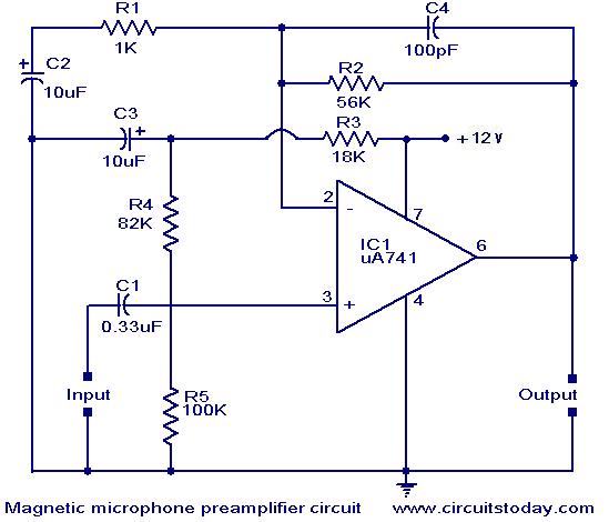
Description: This circuit is an Op-Amp Microphone Preamplifier that operates using a single power supply. It is suitable for both dynamic and electret microphones. The schematic illustrates the configuration with a dynamic microphone; however, for electret microphones, a pair of appropriate biasing resistors is necessary to provide power. The design follows a standard non-inverting configuration, where the input is connected to the non-inverting input of the op-amp, typically pin 3. The input impedance is 23.5 kΩ, and the overall voltage gain is determined by resistors R2 and R1, according to the specified formula.
The Op-Amp Microphone Preamplifier circuit is designed to amplify low-level audio signals from microphones, making it suitable for various audio applications, including recording and live sound reinforcement. The circuit employs a single power supply, simplifying the design and making it more versatile for portable applications.
In the non-inverting configuration, the op-amp amplifies the input signal without inverting its phase. The input signal from the microphone is fed into the non-inverting terminal of the op-amp, allowing for high input impedance, which is crucial for interfacing with microphones that typically have high output impedance. The input impedance of 23.5 kΩ ensures minimal loading on the microphone, preserving the integrity of the audio signal.
For dynamic microphones, the schematic directly connects the microphone output to the non-inverting input of the op-amp. In contrast, electret microphones require additional biasing to operate correctly. This is achieved by connecting a pair of resistors to the power supply, which provides the necessary voltage for the electret microphone while also allowing the audio signal to pass through to the op-amp.
The gain of the amplifier is set by the feedback network formed by resistors R1 and R2. The voltage gain (Av) can be calculated using the formula:
Av = 1 + (R2 / R1)
This formula indicates that the gain is determined by the ratio of the resistors, allowing for easy adjustment according to the desired amplification level. Selecting appropriate values for R1 and R2 is critical for optimizing the performance of the preamplifier and ensuring that the output signal is strong enough for further processing or amplification stages.
Overall, this Op-Amp Microphone Preamplifier circuit is an effective solution for amplifying audio signals with flexibility for different microphone types, making it a valuable component in audio signal processing systems.This is the circuit of Op-Amp Microphone Preamplifier using a single power supply, this circuit suitable for dynamic or electret microphones. Nothing too special here. The Schematic is shown using a dynamic microphone, for use with an electret a pair of suitable biasing resistor is required to power the electret microphone.
The design is a standar d non-inverting design, the input is applied to the non-inverting input of the op-amp, which is pin 3 in most cases. The input impedance is 23. 5k, the overall voltage gain is determined by R2 and R1according to the following formula:
The Op-Amp Microphone Preamplifier circuit is designed to amplify low-level audio signals from microphones, making it suitable for various audio applications, including recording and live sound reinforcement. The circuit employs a single power supply, simplifying the design and making it more versatile for portable applications.
In the non-inverting configuration, the op-amp amplifies the input signal without inverting its phase. The input signal from the microphone is fed into the non-inverting terminal of the op-amp, allowing for high input impedance, which is crucial for interfacing with microphones that typically have high output impedance. The input impedance of 23.5 kΩ ensures minimal loading on the microphone, preserving the integrity of the audio signal.
For dynamic microphones, the schematic directly connects the microphone output to the non-inverting input of the op-amp. In contrast, electret microphones require additional biasing to operate correctly. This is achieved by connecting a pair of resistors to the power supply, which provides the necessary voltage for the electret microphone while also allowing the audio signal to pass through to the op-amp.
The gain of the amplifier is set by the feedback network formed by resistors R1 and R2. The voltage gain (Av) can be calculated using the formula:
Av = 1 + (R2 / R1)
This formula indicates that the gain is determined by the ratio of the resistors, allowing for easy adjustment according to the desired amplification level. Selecting appropriate values for R1 and R2 is critical for optimizing the performance of the preamplifier and ensuring that the output signal is strong enough for further processing or amplification stages.
Overall, this Op-Amp Microphone Preamplifier circuit is an effective solution for amplifying audio signals with flexibility for different microphone types, making it a valuable component in audio signal processing systems.This is the circuit of Op-Amp Microphone Preamplifier using a single power supply, this circuit suitable for dynamic or electret microphones. Nothing too special here. The Schematic is shown using a dynamic microphone, for use with an electret a pair of suitable biasing resistor is required to power the electret microphone.
The design is a standar d non-inverting design, the input is applied to the non-inverting input of the op-amp, which is pin 3 in most cases. The input impedance is 23. 5k, the overall voltage gain is determined by R2 and R1according to the following formula:

op amp Detect real overcurrent/short-circuits vs. current peaks
A MOSFET is employed to drive a load that includes a sense resistor in its current path. The voltage across this resistor is utilized to trigger a circuit capable of disconnecting the load in the event of an overcurrent condition....

Noninverted Unity-Gain Amplifier Circuit
An operational amplifier (op amp) can function as a unity gain amplifier by connecting its output to its inverting input as illustrated. The load resistance (Rl) should be sufficiently low to prevent the op amp's bias current from introducing a...

Power Supply for Preamplifiers (Revision A)
The original version of P05 has been around for a very long time now (around 4 years), and there are some worthwhile reasons for the updates. Although the performance of the original was not lacking in any way, I decided...

Tone Control
A preamplifier circuit featuring independent Bass and Treble tone controls is illustrated in this schematic.
This circuit design utilizes operational amplifiers (op-amps) to achieve independent control over the bass and treble frequencies, allowing for enhanced audio customization. The preamplifier stage amplifies...

Overspeed indicator
An operational amplifier (op-amp) comparator is utilized to compare the output of a converter with a direct current (DC) threshold voltage. The circuit activates an LED when the input frequency surpasses 100 Hz. As the frequency increases, the average current...
Magnetic pickup pre-amplifier circuit
A preamplifier for magnetic pickups of record players is presented. The uA 741 is utilized as an AC-coupled non-inverting amplifier operating on a single supply. The amplifier gain is determined by the feedback components, where C2 manages the low-frequency roll-off...

Vanda F-9500A preamplifier b
Figure 3-2 (b) represents the second half of the circuit, where transistors VT17 to VT31 are configured as power amplifiers and pre-amplifiers. This section is structurally identical to the operational integrated circuit IC2 and includes zero servos. The circuit is...

micprocessor
Audio processors are typically utilized in paging systems and wireless intercoms to amplify microphone signals to a specific level. This amplification can be achieved using either a compressor or a limiter circuit. While compressors exhibit lower distortion characteristics, they are...

Moduler PreamplifierCircuit
High-quality, discrete component design for input and tone control modules to complement the 60-watt MOSFET audio amplifier with a high-quality preamplifier design.
The circuit design focuses on creating a high-fidelity audio preamplifier that enhances the performance of a 60-watt MOSFET audio...