


Simple logarithmic amplifier circuit
#logarithmic amplifier
#LT1012
#op-amp
#voltage input
#low bias current
#signal processing
#analog circuits
#amplifier
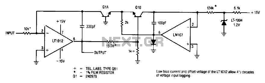
Description: This simple logarithmic amplifier circuit uses the LT1012, which has a low bias current that allows for 4.5 decades of voltage input logging. Additionally, transistors that can be used in this circuit include the 2N2979.
The logarithmic amplifier circuit designed around the LT1012 operational amplifier is a crucial component in applications requiring the conversion of a wide range of input voltages into a logarithmic scale. The LT1012 is characterized by its low bias current, which is essential for achieving high accuracy in logarithmic amplification, particularly over a range of 4.5 decades. This feature minimizes the offset errors that can arise from input bias currents, ensuring that the output closely follows the logarithmic relationship of the input voltage.
In this circuit, the LT1012 is configured in a feedback arrangement that allows the input voltage to be logarithmically processed. The transistors, such as the 2N2979, can be incorporated to enhance the performance of the logarithmic amplifier. The 2N2979 is a high-speed transistor that can be utilized in the feedback loop or as part of the input stage to improve the linearity and response time of the circuit.
The overall design should include careful consideration of the resistor values in the feedback network, as these will dictate the gain and the logarithmic scaling factor. Capacitors may also be included to stabilize the amplifier and filter out any noise that could affect the accuracy of the logarithmic output.
The output of the circuit can be used in various applications, including signal processing, audio level measurement, and any system where a logarithmic representation of the input signal is beneficial. Proper layout and component selection are critical to ensure minimal distortion and optimal performance of the logarithmic amplifier circuit.This simple logarithmic amplifier circuit use the LT1012 which has a low bias current allow 4 1/2 decades off voltage input logging. Transistors that can be used here could be the 2N2979..
The logarithmic amplifier circuit designed around the LT1012 operational amplifier is a crucial component in applications requiring the conversion of a wide range of input voltages into a logarithmic scale. The LT1012 is characterized by its low bias current, which is essential for achieving high accuracy in logarithmic amplification, particularly over a range of 4.5 decades. This feature minimizes the offset errors that can arise from input bias currents, ensuring that the output closely follows the logarithmic relationship of the input voltage.
In this circuit, the LT1012 is configured in a feedback arrangement that allows the input voltage to be logarithmically processed. The transistors, such as the 2N2979, can be incorporated to enhance the performance of the logarithmic amplifier. The 2N2979 is a high-speed transistor that can be utilized in the feedback loop or as part of the input stage to improve the linearity and response time of the circuit.
The overall design should include careful consideration of the resistor values in the feedback network, as these will dictate the gain and the logarithmic scaling factor. Capacitors may also be included to stabilize the amplifier and filter out any noise that could affect the accuracy of the logarithmic output.
The output of the circuit can be used in various applications, including signal processing, audio level measurement, and any system where a logarithmic representation of the input signal is beneficial. Proper layout and component selection are critical to ensure minimal distortion and optimal performance of the logarithmic amplifier circuit.This simple logarithmic amplifier circuit use the LT1012 which has a low bias current allow 4 1/2 decades off voltage input logging. Transistors that can be used here could be the 2N2979..

Inverting-programmable-gain-amplifier
This circuit can be programmed for a gain of 0, -1, -2, -4, or -8. This could also be accomplished with one input resistor and one feedback resistor per channel in the conventional manner, but this would require eight resistors...
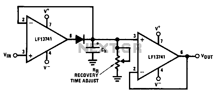
Low-drift-peak-detector
This circuit utilizes operational amplifier U1 to correct the offset in the peak detector diode D1. The voltage across capacitor C is the precise peak voltage. Additionally, U2 functions as a voltage follower to measure this voltage.
The described circuit employs...

DOD Phasor 595
Protection against reverse voltage is implemented. A 10µF capacitor provides additional DC filtering. The CD4007 is configured as a flip-flop controlled by a foot switch. The output of the flip-flop drives the indicator. An 18V supply passes through a 100kΩ...

Capacitor Allows Higher Slew Rates
In this circuit, a Burr-Brown operational amplifier provides a slew rate of 135 V/μs. The inclusion of capacitor C2 reduces the high-frequency feedback factor to less than unity, enabling higher slew-rate amplifiers to be compensated for gains greater than one.
This...
op amp Why the resistor in this op-amp circuit
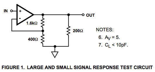
Here is a circuit diagram for a signal response test circuit from the specification sheet for a HA-5195 operational amplifier. It appears to be a non-inverting amplifier circuit with a gain of 5, along with a 200-ohm resistor connecting Vout...

Classic-op-amp-astable-multivibrator
This circuit utilizes the CA3130 BiMOS operational amplifier, which operates at a frequency of 1 kHz. It features a rail-to-rail output swing, ensuring that the output can reach the supply voltage levels. The frequency of operation remains independent of supply...

Amplifier Output Delay with Relay Schematic Diagram
This is a minimal circuit designed for individual audio amplifier projects to control the presenter output relay. The purpose of this circuit is to manage the relay that activates the speaker output within the audio amplifier. The circuit introduces a...

Improved non-inverting integrator
In the circuit depicted in Figure 1, ICla generates the integral term required for operation, but it also inadvertently produces an unnecessary proportional term. This proportional term is countered by IClb, resulting in a pure integral output. If the ratio...

a better sine wave
The operational amplifier (op-amp) is configured for 50x amplification, functioning similarly to a comparator. With this setup, a 50 mV deviation from the 2.5V reference will push the output to its limits. The output signal resembles a heavily clipped sine...