


Simple Peak Detector Circuit schematic with explanation
#peak detector
#op-amp
#1458 IC
#voltage follower
#capacitor
#diode
#signal processing
#analog circuit
#maximum voltage detection

Description: The circuit utilizes a dual operational amplifier integrated circuit (IC), specifically the 1458, which contains two separate op-amps within a single package. In this configuration, the first op-amp functions as a voltage follower, directing its output to charge capacitor C1 through diode D1. Consequently, the voltage to which capacitor C1 charges is equivalent to the peak voltage of the input waveform. The second op-amp within the 1458 acts as a buffer, providing the voltage from the capacitor with minimal loss in charge. A reset switch is incorporated to discharge the capacitor when a new input peak voltage requires detection.
The circuit design effectively employs the 1458 dual operational amplifier to achieve peak voltage detection from an input waveform. The first op-amp, configured as a voltage follower, ensures that the output voltage closely follows the input voltage, allowing for efficient charging of capacitor C1. This configuration is crucial for accurately capturing the peak voltage of the input signal, as the voltage across C1 will reflect this maximum value.
The diode D1 plays a vital role in preventing the discharge of C1 back into the op-amp, ensuring that the capacitor retains its charge after reaching the peak voltage. This characteristic is particularly important in applications where the peak voltage must be maintained for further processing or analysis.
The second op-amp serves as a buffer, isolating the capacitor from the subsequent circuitry. This buffering action minimizes any load effects that could result in voltage drops, thereby preserving the integrity of the voltage stored in C1. This feature is essential for applications requiring precise voltage levels.
The reset switch allows for manual intervention to discharge the capacitor. This functionality is important for applications that need to detect new peak voltages at irregular intervals. By discharging C1, the circuit can be reset and prepared to capture the next peak voltage accurately.
Overall, this circuit design demonstrates an efficient method for peak voltage detection using a dual op-amp configuration, ensuring accurate voltage tracking and minimal signal degradation. The combination of a voltage follower, buffer, and reset mechanism provides a robust solution for various electronic applications requiring peak voltage monitoring.The circuit uses a dual operational amplifier IC, the 1458, which is a single IC package that houses two individual op-amps. In this circuit, the first op-amp is used as a voltage follower whose output is used to charge the capacitor C1 through D1.
As such, the voltage to which capacitor C1 charges up to is the maximum voltage that the input wavef orm reached, i. e. , its peak voltage. The second op-amp of the 1458 is used as a buffer that outputs the capacitor voltage with negligible loss in the capacitor charge. The reset switch is used to discharge the capacitor if a new input peak voltage needs to be detected.
The circuit design effectively employs the 1458 dual operational amplifier to achieve peak voltage detection from an input waveform. The first op-amp, configured as a voltage follower, ensures that the output voltage closely follows the input voltage, allowing for efficient charging of capacitor C1. This configuration is crucial for accurately capturing the peak voltage of the input signal, as the voltage across C1 will reflect this maximum value.
The diode D1 plays a vital role in preventing the discharge of C1 back into the op-amp, ensuring that the capacitor retains its charge after reaching the peak voltage. This characteristic is particularly important in applications where the peak voltage must be maintained for further processing or analysis.
The second op-amp serves as a buffer, isolating the capacitor from the subsequent circuitry. This buffering action minimizes any load effects that could result in voltage drops, thereby preserving the integrity of the voltage stored in C1. This feature is essential for applications requiring precise voltage levels.
The reset switch allows for manual intervention to discharge the capacitor. This functionality is important for applications that need to detect new peak voltages at irregular intervals. By discharging C1, the circuit can be reset and prepared to capture the next peak voltage accurately.
Overall, this circuit design demonstrates an efficient method for peak voltage detection using a dual op-amp configuration, ensuring accurate voltage tracking and minimal signal degradation. The combination of a voltage follower, buffer, and reset mechanism provides a robust solution for various electronic applications requiring peak voltage monitoring.The circuit uses a dual operational amplifier IC, the 1458, which is a single IC package that houses two individual op-amps. In this circuit, the first op-amp is used as a voltage follower whose output is used to charge the capacitor C1 through D1.
As such, the voltage to which capacitor C1 charges up to is the maximum voltage that the input wavef orm reached, i. e. , its peak voltage. The second op-amp of the 1458 is used as a buffer that outputs the capacitor voltage with negligible loss in the capacitor charge. The reset switch is used to discharge the capacitor if a new input peak voltage needs to be detected.

Simple Op-Amp Radio
The following schematic illustrates the Simple Op-Amp Radio Circuit Diagram sourced from bowdenshobbycircuits.info. This Simple Op-Amp Radio essentially functions as a crystal radio.
The Simple Op-Amp Radio Circuit utilizes an operational amplifier (op-amp) to enhance the performance of a basic crystal...

op amp Find Vo in an op-amp transistor circuit
The voltage measured at 12V after the emitter is perplexing, especially when the output from the op-amp is +15V, suggesting a 3V drop across the transistor. This raises questions about the expected gain of 2, which would imply an output...

Glitch-Free Clipper
A simple clamping circuit can be added to a Harris 2620 high-speed operational amplifier (op-amp) to create a glitch-free amplifier and clipper. The pin that controls the device's bandwidth is a high-impedance, isolated input, which also tracks the output voltage...

vtx 1800c diode fix
This document provides a guide for creating and installing a diode kit on a Honda VTX 1800C motorcycle. This installation is essential when replacing incandescent turn signals with LED lights.
The installation of a diode kit is a critical step when...

Karplus Strong Opamp Circuit
It is essentially an all-pass filter with two additional components: a capacitor and a resistor, which produces percussion sounds. A schematic of the unmodified all-pass filter circuit, a waveform captured via Audacity, and a short audio sample featuring a drum...
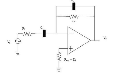
Differentiator Op Amp Circuit
The differentiator circuit is an application circuit derived from mathematical principles influenced by capacitor behavior. The circuit, as illustrated in the accompanying image, is a simple differentiator configuration. To derive the differentiator formula, the following sequence is used: Ic =...

sweep
The diode D13 is responsible for providing different timings for the forward sweep and the retrace, with the retrace occurring at a faster rate than the forward sweep. It generates outputs that inform the blanking circuit when to blank and...

Dynamo Frequency Monitor
IC1 is a dual operational amplifier. In this circuit, each op-amp functions as a voltage comparator. When the voltage at the positive input exceeds the voltage at the negative input, the output transitions to a high state. Conversely, when the...
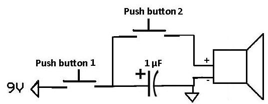
Apply a Pulse to a Speaker Using a Capacitor
This project demonstrates how a capacitor can supply a pulse signal to a speaker. A capacitor is charged and then discharges its voltage to a speaker, which acts as a transducer that converts electrical signals into sound. The result is...