


Sound trigger for flash unit
#sound trigger
#flash unit
#operational amplifier
#microphone
#triac
#amplifier
#strobe
#sensitivity
#trigger current

Description: The circuit utilizes an operational amplifier (IC1) configured in a non-inverting amplifier mode. Resistors R1 and R2 establish a gain of approximately 500. The variable resistor RV1 (sensitivity) adjusts the bias of the non-inverting input to the negative supply voltage. Transistor Q1 supplies the necessary high trigger current for the triac. When the microphone detects a sound signal, IC1 amplifies this signal, triggering the triac. This results in a low-resistance path across its A1 and A2 terminals, which are connected through the flash lead to the strobe. The circuit operates with minimal delay, ensuring that the flashgun is activated almost instantaneously upon sound detection.
The circuit design primarily revolves around the operational amplifier IC1, which is critical for amplifying the audio signal captured by the microphone. The configuration of the op-amp in the non-inverting mode allows for a high input impedance, ensuring that the microphone's output is not loaded down, while also providing significant gain due to the resistor network formed by R1 and R2. The gain of 500 indicates that even low-level audio signals can be effectively amplified to a level sufficient to trigger the triac.
The sensitivity of the circuit can be fine-tuned using RV1, which adjusts the voltage at the non-inverting input. This adjustment is crucial for adapting the circuit to different sound levels, allowing it to respond appropriately to varying audio inputs. The biasing of the non-inverting input to the negative supply ensures that the op-amp operates within its linear region, providing consistent amplification without distortion.
Transistor Q1 plays a pivotal role in the circuit by providing the necessary trigger current to the triac. Triacs are semiconductor devices that can control high power loads and are commonly used in applications like flash photography. When the amplified audio signal reaches a certain threshold, Q1 turns on, allowing current to flow through the triac, which then closes the circuit across its A1 and A2 terminals. This action effectively connects the strobe to the power source, enabling it to flash.
The overall design of the circuit is optimized for rapid response, with the operational amplifier and triac working in tandem to ensure that the flashgun is triggered almost instantaneously after the sound is detected. This feature is particularly advantageous in applications such as photography, where timing is critical for capturing fleeting moments. The minimal delay between sound detection and flash activation enhances the circuit's usability in dynamic environments.The circuit is based on operational amplifier IC1 used in the noninverting amplifier mode. Rl and 2 set the gain at about 500. RV1 (sensitivity) biases the noninverting input to the negative supply. Ql provides the relatively high trigger current required by the triac. When a signal is received by the microphone, the signals are amplified (by IC1). The triac is triggered and a low resistance appears across its Al and A2 terminals which are connected via the fiashlead to the strobe. The circuit operates almost instantly, giving very little delay between the commencement of the sound and the flashgun being triggered.
The circuit design primarily revolves around the operational amplifier IC1, which is critical for amplifying the audio signal captured by the microphone. The configuration of the op-amp in the non-inverting mode allows for a high input impedance, ensuring that the microphone's output is not loaded down, while also providing significant gain due to the resistor network formed by R1 and R2. The gain of 500 indicates that even low-level audio signals can be effectively amplified to a level sufficient to trigger the triac.
The sensitivity of the circuit can be fine-tuned using RV1, which adjusts the voltage at the non-inverting input. This adjustment is crucial for adapting the circuit to different sound levels, allowing it to respond appropriately to varying audio inputs. The biasing of the non-inverting input to the negative supply ensures that the op-amp operates within its linear region, providing consistent amplification without distortion.
Transistor Q1 plays a pivotal role in the circuit by providing the necessary trigger current to the triac. Triacs are semiconductor devices that can control high power loads and are commonly used in applications like flash photography. When the amplified audio signal reaches a certain threshold, Q1 turns on, allowing current to flow through the triac, which then closes the circuit across its A1 and A2 terminals. This action effectively connects the strobe to the power source, enabling it to flash.
The overall design of the circuit is optimized for rapid response, with the operational amplifier and triac working in tandem to ensure that the flashgun is triggered almost instantaneously after the sound is detected. This feature is particularly advantageous in applications such as photography, where timing is critical for capturing fleeting moments. The minimal delay between sound detection and flash activation enhances the circuit's usability in dynamic environments.The circuit is based on operational amplifier IC1 used in the noninverting amplifier mode. Rl and 2 set the gain at about 500. RV1 (sensitivity) biases the noninverting input to the negative supply. Ql provides the relatively high trigger current required by the triac. When a signal is received by the microphone, the signals are amplified (by IC1). The triac is triggered and a low resistance appears across its Al and A2 terminals which are connected via the fiashlead to the strobe. The circuit operates almost instantly, giving very little delay between the commencement of the sound and the flashgun being triggered.

nokia 6630 microphone problem picture
The microphone issue on the Nokia 6630 is typically attributed to several factors, including a damaged microphone, a broken circuit path, or a faulty UEM IC. If the issue arises from a broken path in the microphone circuit, it is...

Carbon Mic Replacement To Magnetic Mike Converter Circuit
Effective pitching surpasses effective hitting, and a high-quality magnetic microphone outperforms a carbon microphone. This circuit utilizes a single transistor to convert a carbon microphone input into a magnetic microphone output. It is important to note that no ground connection...

gated pulse descrambler
This circuit consists of an amplifier and a video detector with a second subcarrier detector for synchronization recovery purposes. A pulse-former circuit modulates the gain of the main channel, increasing it during synchronization intervals.
The circuit is designed to enhance video...

Bird Feeder Monitor Circuit
The first amplifier circuit is a bird phone. In this circuit, the electret microphone (MIC1) is mounted in the neck of a large plastic funnel. The amplifier, built around an MC34119, is then placed outside of the funnel with the...

Self Oscillating Amplifier for Distortion Testing
The circuit is based on a simple inductor-capacitor filter circuit, and needs only a pot and a small light bulb to set and stabilise the oscillation. The frequency is fixed, and with a good inductor should be capable of very...

Microphone Circuit-PC Sound Card
This microphone circuit was submitted by Lazar Pancic from Yugoslavia. The sound card for a PC typically features a microphone input, speaker output, and occasionally line inputs and outputs. The microphone input is designed specifically for dynamic microphones with an...
Portable Microphone Preamplifier
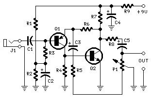
Cleaned Input: This circuit is mainly intended to provide common home stereo amplifiers with a microphone input. The battery supply is a good compromise: in this manner the input circuit is free from mains low frequency hum pick-up and connection...

iPod/MP3 Mini Speaker System
Listen and share music wherever you go with the mini speaker system project. This project allows for music playback in various locations such as dorms, cubicles, or the beach. It serves as an excellent introduction to circuit systems, featuring an...

gic
The design resembles a combination of circuits from M49 and U47, utilizing the tube from U67. It features a true variable-pattern microphone capable of omnidirectional, cardioid, and figure-of-eight patterns. This is achieved by polarizing the front and back diaphragms of...