


TDA8351 8356 application circuit

Description: The figure illustrates the actual application circuit for the TDA8351/8356. In this circuit, a 50V voltage feedback (VFB) is connected in series with a 33-ohm resistor. Signals are input at pins 1 and 2, where pin 1 receives a positive sawtooth voltage signal and pin 2 receives a negative sawtooth voltage signal. A resistor, Rcon, is placed in parallel between pins 1 and 2 to determine the deflection current flowing through the coil. The circuit employs an internal differential amplifier followed by a push-pull power amplifier, which drives the deflection coil through pin 7 (output) and pin 4 (negative sawtooth voltage). Additionally, a resistor RM is connected in series with the deflection coil, which is influenced by the feedback voltage input at pin 9. This configuration enhances the linearity of the sawtooth output and expands the dynamic range of the sawtooth waveform.
The TDA8351/8356 application circuit is designed for use in television and display systems, where precise control of deflection currents is essential for image stability and quality. The circuit operates by generating opposing sawtooth voltage signals at pins 1 and 2, which are crucial for controlling the deflection coils in cathode-ray tubes (CRTs) or similar display technologies. The resistor Rcon, situated between the input pins, plays a vital role in regulating the current through the deflection coils, ensuring accurate deflection of the electron beam.
The internal differential amplifier processes the input signals, amplifying the difference between them, which is then fed into a push-pull output stage. This configuration allows for efficient driving of the deflection coils, providing a strong and responsive control signal. The output at pin 7 produces a positive sawtooth waveform, while pin 4 delivers the corresponding negative sawtooth waveform, creating the necessary alternating current for deflection.
The inclusion of the feedback resistor RM is critical for improving the linearity of the output waveforms. By connecting RM in series with the deflection coil, the circuit can adjust the feedback voltage at pin 9, enhancing the performance of the sawtooth generator. This feedback loop not only stabilizes the output but also broadens the dynamic range, allowing for more precise control over the deflection process.
Overall, the TDA8351/8356 application circuit exemplifies a sophisticated approach to managing voltage signals for display applications, ensuring that the generated waveforms are both linear and dynamic, which is essential for high-quality image rendering. As shown in the figure shows the actual application circuit TDA8351/8356, when the 50V VFB 60V, VFB in series with the input of a 33 resistor. Signals are input 1,2 feet, these are two sawtooth voltage signal opposite in phase, positive sawtooth voltage input pin 1, pin 2 negative sawtooth voltage input. 1,2 feet between a resistor in parallel Rcon to determine the deflection current through the coil. After an internal signal of the differential amplifier and push-pull power amplifier output to the deflection by a 7,4 feet across the coil.
7 feet sawtooth voltage waveform pulse, 4 feet sawtooth voltage waveform is negative. RM resistor in series with the deflection coil, provided by the feedback voltage input pin 9, the linear sawtooth output is improved, and expand the dynamic range of the sawtooth wave.
The TDA8351/8356 application circuit is designed for use in television and display systems, where precise control of deflection currents is essential for image stability and quality. The circuit operates by generating opposing sawtooth voltage signals at pins 1 and 2, which are crucial for controlling the deflection coils in cathode-ray tubes (CRTs) or similar display technologies. The resistor Rcon, situated between the input pins, plays a vital role in regulating the current through the deflection coils, ensuring accurate deflection of the electron beam.
The internal differential amplifier processes the input signals, amplifying the difference between them, which is then fed into a push-pull output stage. This configuration allows for efficient driving of the deflection coils, providing a strong and responsive control signal. The output at pin 7 produces a positive sawtooth waveform, while pin 4 delivers the corresponding negative sawtooth waveform, creating the necessary alternating current for deflection.
The inclusion of the feedback resistor RM is critical for improving the linearity of the output waveforms. By connecting RM in series with the deflection coil, the circuit can adjust the feedback voltage at pin 9, enhancing the performance of the sawtooth generator. This feedback loop not only stabilizes the output but also broadens the dynamic range, allowing for more precise control over the deflection process.
Overall, the TDA8351/8356 application circuit exemplifies a sophisticated approach to managing voltage signals for display applications, ensuring that the generated waveforms are both linear and dynamic, which is essential for high-quality image rendering. As shown in the figure shows the actual application circuit TDA8351/8356, when the 50V VFB 60V, VFB in series with the input of a 33 resistor. Signals are input 1,2 feet, these are two sawtooth voltage signal opposite in phase, positive sawtooth voltage input pin 1, pin 2 negative sawtooth voltage input. 1,2 feet between a resistor in parallel Rcon to determine the deflection current through the coil. After an internal signal of the differential amplifier and push-pull power amplifier output to the deflection by a 7,4 feet across the coil.
7 feet sawtooth voltage waveform pulse, 4 feet sawtooth voltage waveform is negative. RM resistor in series with the deflection coil, provided by the feedback voltage input pin 9, the linear sawtooth output is improved, and expand the dynamic range of the sawtooth wave.
amplifier timer circuit schematic
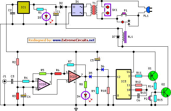
This circuit deactivates an amplifier or any connected device when a low-level audio signal at its input is absent for at least 15 minutes. By pressing P1, the device is powered on, supplying power to any appliance connected to SK1....

Bassman Modifications
Upgrading to a 3-prong AC cord is a common modification, as is the replacement of filter capacitors. Switching coupling capacitors to brands like Orange Drops or other boutique options is also popular, often enhancing the appeal in online auctions. Additional...

Amplifier Timer Circuit Schematic
This circuit turns off an amplifier or any other device when it remains idle for 15 minutes. It is powered by the amplifier's tape output.
The described circuit functions as an automatic power management system, designed to enhance energy efficiency by...

Amplifier Timer Circuit Schematic
This circuit deactivates an amplifier or any connected device when a low-level audio signal at its input is absent for at least 15 minutes. Pressing P1 turns the device on, supplying power to any appliance connected to SK1. The input...

Ears and Speakers Protector
Occasionally, the output volume of an amplifier can be excessively high, leading to discomfort and potential damage to both the listener's ears and the loudspeaker. The circuit...
Amplifiers are crucial components in audio systems, responsible for boosting audio signals to drive...

USB Powered Audio Power Amplifier
This circuit for multimedia speakers designed for PCs utilizes a single-chip architecture, operates on a low-voltage power supply, is compatible with USB power, facilitates easy heat dissipation, is cost-effective, offers high flexibility, and has a wide temperature tolerance. Central to...

Self Oscillating Amplifier for Distortion Testing
The circuit is based on a simple inductor-capacitor filter circuit, and needs only a pot and a small light bulb to set and stabilise the oscillation. The frequency is fixed, and with a good inductor should be capable of very...

Emitter negative feedback differential amplifier gain control circuit
A controllable gain amplifier functions as an automatic gain control circuit within the execution unit. The primary methods for controlling the amplifier's gain involve two approaches: one is by adjusting certain parameters of the amplifier itself, such as emitter current,...
Amplifier Cool-Down Circuit Circuit
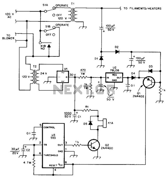
This cool-down relay circuit utilizes an integrated circuit (IC) timer to control a relay, which maintains the operation of the blower for a specified time delay determined by timer U3. The capacitance value of C2 can be adjusted to either...