


The basic circuit diagram of a differentiator
#differentiator
#op-amp
#analog circuit
#signal processing
#feedback
#capacitor
#resistor
#input-output relationship
#basic circuit
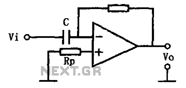
Description: This circuit illustrates a basic differentiating circuit. The differential operation circuit can process input and output signals, establishing a relationship between the output and the input.
A basic differentiating circuit is designed to produce an output that is proportional to the rate of change of the input signal. In electronic applications, this is particularly useful for processing signals where rapid changes need to be detected, such as in waveform shaping or signal conditioning.
The circuit typically consists of a resistor (R) and a capacitor (C) arranged in a configuration that allows the differentiation of the input voltage (Vin). The output voltage (Vout) is derived across the resistor, and the relationship can be expressed mathematically as Vout = -RC(dVin/dt), where dVin/dt represents the derivative of the input voltage with respect to time. This indicates that the output voltage is inversely proportional to the rate of change of the input voltage.
In practical implementations, the values of R and C must be carefully selected to ensure that the circuit responds appropriately to the frequencies of interest. A high-pass filter characteristic is inherent in this differentiating circuit, allowing high-frequency signals to pass while attenuating low-frequency signals.
The circuit can be further enhanced by incorporating operational amplifiers (op-amps) to improve performance, increase gain, and provide better control over the output characteristics. By using an op-amp in a differentiating configuration, the circuit can achieve greater accuracy and stability, as well as the ability to handle a wider range of input signal amplitudes.
In summary, the basic differentiating circuit serves as a fundamental building block in various electronic applications, enabling the detection and amplification of rapid changes in input signals. As shown for the basic differentiating circuit. The differential operation circuit can input and output, the relationship between the output, between the input:
A basic differentiating circuit is designed to produce an output that is proportional to the rate of change of the input signal. In electronic applications, this is particularly useful for processing signals where rapid changes need to be detected, such as in waveform shaping or signal conditioning.
The circuit typically consists of a resistor (R) and a capacitor (C) arranged in a configuration that allows the differentiation of the input voltage (Vin). The output voltage (Vout) is derived across the resistor, and the relationship can be expressed mathematically as Vout = -RC(dVin/dt), where dVin/dt represents the derivative of the input voltage with respect to time. This indicates that the output voltage is inversely proportional to the rate of change of the input voltage.
In practical implementations, the values of R and C must be carefully selected to ensure that the circuit responds appropriately to the frequencies of interest. A high-pass filter characteristic is inherent in this differentiating circuit, allowing high-frequency signals to pass while attenuating low-frequency signals.
The circuit can be further enhanced by incorporating operational amplifiers (op-amps) to improve performance, increase gain, and provide better control over the output characteristics. By using an op-amp in a differentiating configuration, the circuit can achieve greater accuracy and stability, as well as the ability to handle a wider range of input signal amplitudes.
In summary, the basic differentiating circuit serves as a fundamental building block in various electronic applications, enabling the detection and amplification of rapid changes in input signals. As shown for the basic differentiating circuit. The differential operation circuit can input and output, the relationship between the output, between the input:

Op-Amp Application: Level Shifting Amplifier
In linear equipment design, it is sometimes necessary to take a voltage that is referenced to a certain DC level and generate an amplified output that is also referenced.
In linear circuit design, the process of amplifying a voltage that is...

Op Amp based Hartley oscillator
Construct an oscillator that meets several specifications. The primary requirement is to incorporate exactly one capacitor. Another requirement is to achieve a high quality factor (Q) and produce a sine wave output. The design under consideration is Hartley’s oscillator, which...

OP-AMP or comparator Astable multivibrator
Simulation schematic for an astable multivibrator. Parameters: Vcc = 24V, Vol = 1V, Voh = 21V. The power supply is Vcc, with connections from Vcc to ground. The time constant is determined by R1 and the capacitor C1, where R1...

Polarity Gain Adjustment Circuit
By adjusting one potentiometer, the output of this circuit can be varied from a positive version of the input signal, smoothly transitioning through zero output, and then to a negative version of the input. For instance, if the input signal...

Audio Signal Clipping Indicator
A window comparator formed by two operational amplifiers packaged into IC1 is the heart of the circuit below. With this technique, we can detect precisely and symmetrically.
The window comparator circuit utilizes two operational amplifiers (op-amps) configured to create a defined...

Anti-Log Converter
Anti-log or exponential generation involves rearranging logarithmic circuitry. The circuit diagram below illustrates the relevant circuitry.
Anti-logarithmic or exponential circuits are essential in various applications, particularly in signal processing and analog computing. These circuits typically utilize operational amplifiers (op-amps) configured in...

Audio Triangle Square Wave Generator Using Op-Amp
The circuit illustrates a straightforward triangle and square wave generator utilizing a common dual operational amplifier, the LM1558, capable of producing very low frequencies around 10 kHz. The time interval for one half-cycle is approximately determined by the product of...

High Impedance DC Voltmeter Circuit Using Op Amp
This design outlines a high impedance DC voltmeter circuit utilizing the uA741 integrated circuit (IC). The uA741 is configured as a non-inverting DC amplifier. The circuit incorporates negative feedback through a DC meter that requires 1 mA for full-scale deflection....

3 Band Graphic Equalizer
This simple equalizer utilizes a single operational amplifier (op-amp) and provides three frequency ranges: low frequency, mid frequency, and high frequency. With the specified component values, it achieves approximately ±20 dB of gain or attenuation at frequencies of 50 Hz,...