


The MAX4108 4109 4308 4309 large capacitive load drive circuit diagram to enlarge
#MAX4108
#MAX4109
#MAX4308
#MAX4309
#capacitive load
#driving circuit
#isolation resistor
#AC characteristics
#amplifier

Description: The circuit depicted in the figure employs the MAX4108/4109/4308/4309 operational amplifiers with a capacitive load driving circuit isolation resistor (Rs). While the MAX4108/4109/4308/4309 exhibits excellent AC characteristics, it is not optimized for driving high-load electrical resistances. A significant reactive load can diminish the phase margin, leading to overshoot and ringing in pulse signals. To mitigate these issues, an isolation resistor (Rs) is added between the output terminals and the load. The recommended resistance value for Rs is between 15 to 20 ohms.
The MAX4108/4109/4308/4309 series of operational amplifiers are designed for high-speed applications, providing low distortion and high bandwidth. In scenarios where these amplifiers are tasked with driving capacitive loads, the inherent capacitance can interact negatively with the output stage of the amplifier, resulting in stability issues. The addition of an isolation resistor, Rs, serves a critical role in enhancing the stability of the circuit by dampening potential oscillations that arise from the interaction between the amplifier and the capacitive load.
The value of Rs, typically chosen between 15 to 20 ohms, is a compromise that balances the need to suppress overshoot without significantly affecting the output signal's integrity. A resistor value that is too high may introduce additional signal attenuation, while a value that is too low may fail to sufficiently dampen the overshoot and ringing. The choice of Rs should be validated through simulation or empirical testing to ensure optimal performance in the specific application context.
In practical applications, the layout of the circuit should also be considered to minimize parasitic inductance and capacitance, which can further exacerbate oscillation issues. Proper grounding techniques and short trace lengths between the amplifier output and the load can significantly improve stability. Additionally, the use of bypass capacitors near the power supply pins of the operational amplifiers can help maintain a stable voltage supply, further enhancing performance.
Overall, the implementation of an isolation resistor in conjunction with the MAX4108/4109/4308/4309 amplifiers is a well-established technique for ensuring reliable operation in environments where capacitive loads are present, thus maintaining signal integrity and system performance. As shown in FIG grounds MAX4108/4109/4308/4309 using the capacitive load driving circuit isolation resistor Rs constituted. MAX4108/4109/4308/4309 good AC characteristics, but it is not designed to drive high-load electrical resistance, its high reactive load will reduce its phase margin, causing a pulse signal overshoot ringing and ringing. The circuit between the output terminals and the load plus an isolation resistor Rs, for suppressing overshoot and ringing oscillations, Rs resistance is 15 ~ 20 .
The MAX4108/4109/4308/4309 series of operational amplifiers are designed for high-speed applications, providing low distortion and high bandwidth. In scenarios where these amplifiers are tasked with driving capacitive loads, the inherent capacitance can interact negatively with the output stage of the amplifier, resulting in stability issues. The addition of an isolation resistor, Rs, serves a critical role in enhancing the stability of the circuit by dampening potential oscillations that arise from the interaction between the amplifier and the capacitive load.
The value of Rs, typically chosen between 15 to 20 ohms, is a compromise that balances the need to suppress overshoot without significantly affecting the output signal's integrity. A resistor value that is too high may introduce additional signal attenuation, while a value that is too low may fail to sufficiently dampen the overshoot and ringing. The choice of Rs should be validated through simulation or empirical testing to ensure optimal performance in the specific application context.
In practical applications, the layout of the circuit should also be considered to minimize parasitic inductance and capacitance, which can further exacerbate oscillation issues. Proper grounding techniques and short trace lengths between the amplifier output and the load can significantly improve stability. Additionally, the use of bypass capacitors near the power supply pins of the operational amplifiers can help maintain a stable voltage supply, further enhancing performance.
Overall, the implementation of an isolation resistor in conjunction with the MAX4108/4109/4308/4309 amplifiers is a well-established technique for ensuring reliable operation in environments where capacitive loads are present, thus maintaining signal integrity and system performance. As shown in FIG grounds MAX4108/4109/4308/4309 using the capacitive load driving circuit isolation resistor Rs constituted. MAX4108/4109/4308/4309 good AC characteristics, but it is not designed to drive high-load electrical resistance, its high reactive load will reduce its phase margin, causing a pulse signal overshoot ringing and ringing. The circuit between the output terminals and the load plus an isolation resistor Rs, for suppressing overshoot and ringing oscillations, Rs resistance is 15 ~ 20 .
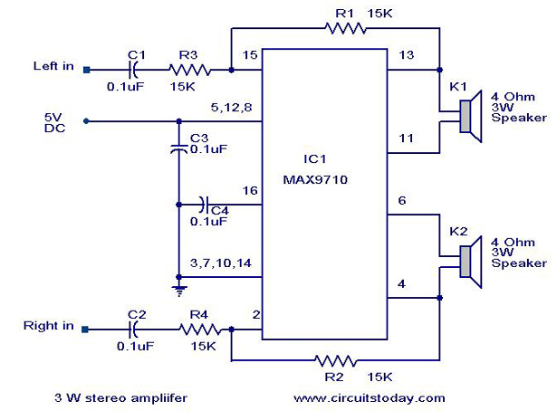
3 W Stereo amplifier using MAX 7910-Audio power amplifier circuit
An audio power amplifier circuit for a 3-watt stereo amplifier using the MAX 7910 IC is explained below.
The audio power amplifier circuit utilizing the MAX 7910 IC is designed to deliver a maximum output power of 3 watts per channel...

USB Powered Audio Power Amplifier
This circuit for multimedia speakers designed for PCs utilizes a single-chip architecture, operates on a low-voltage power supply, is compatible with USB power, facilitates easy heat dissipation, is cost-effective, offers high flexibility, and has a wide temperature tolerance. Central to...

Amplifier Timer Circuit
This circuit turns off an amplifier or any other device when a low-level audio signal fed to its input is absent for at least 15 minutes. By pressing P1, the device is powered on, supplying power to any appliance connected...

audio amp
Install the red LED at D2. Align the flat side of the LED with the PCB outline. Install a jumper wire at R4 and install a 220µF electrolytic capacitor at C8 with the negative side connected to ground. Connect pin...
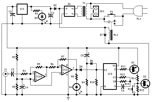
Amplifier Timer
This circuit deactivates an amplifier or other devices when a low-level audio signal at its input is absent for at least 15 minutes. By pressing P1, the device is activated, supplying power to any appliance connected to SK1. The input...

amplifier delay output relay
This is a simple circuit which I built to one of my audio amplifier projects to control the speaker output relay. The purpose of this circuit is to control the relay which turns on the speaker output relay in the...

Amplifier Compressor MC3340P
The output is rectified, and TR2 controls the gain of the ICL. This audio compressor circuit uses an MC3340P as a variable gain amplifier.
The audio compressor circuit described utilizes an MC3340P integrated circuit, which functions as a variable gain amplifier...

Power Supply For Amplifiers
For the 60W amplifier, a nominal (full load) supply of +/- 35V is required, so a 25-0-25 secondary is ideal - however, see Updates, below. The circuit for the supply is shown below, and uses separate rectifiers, capacitors and fuses...
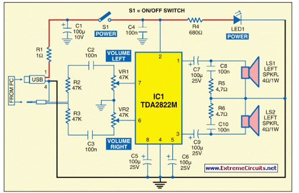
USB Powered Audio Power Amplifier
This circuit of multimedia speakers for PCs features a single-chip design, operates on a low-voltage power supply, is compatible with USB power, and allows for easy heat dissipation.
The multimedia speaker circuit is designed to enhance audio output for personal computers,...