


Wideband-instrumentation-amplifier
#wideband
#instrumentation amplifier
#CA3130
#BiMOS
#dual-gate MOSFET
#40673
#single-supply
#high-frequency
#gain

Description: The circuit features an input resistance of 1 MΩ, a bandwidth extending from DC to approximately 35 MHz, and a gain of 10 times. Low-frequency gain is achieved using a CA3130 BiMOS operational amplifier configured as a single-supply amplifier. High-frequency gain is provided by a 40673 dual-gate MOSFET. The entire amplifier can be nulled by shorting the input to ground and adjusting resistor R9 to achieve zero DC output voltage.
The described circuit serves as a versatile amplifier capable of handling a wide range of frequencies. The CA3130 BiMOS op-amp is well-suited for low-frequency applications due to its high input impedance and low noise characteristics. Operating as a single-supply amplifier allows for simplified power supply requirements, making the design more compact and easier to integrate into various systems.
For high-frequency applications, the 40673 dual-gate MOSFET plays a crucial role in providing additional gain. This MOSFET configuration is particularly effective in RF applications, where maintaining signal integrity at higher frequencies is essential. The dual-gate configuration allows for improved control over the gain and enhances the amplifier's overall performance.
The adjustment process for nulling the amplifier is straightforward. By shorting the input to ground, any offset voltage at the output can be compensated by adjusting R9. This ensures that the amplifier operates at the desired output level, minimizing any DC offset that could affect performance.
Overall, this amplifier circuit is designed for applications requiring a combination of low and high-frequency amplification while maintaining a stable output. The careful selection of components and the ability to null the output voltage enhance the reliability and effectiveness of the circuit in various electronic systems.Has an input resistance of 1-MO, a bandwidth from de to about 35 MHz, and a gain of 10 times. Lowfrequency gain is provided by a CA3130 BiMOS op amp operated as a single-supply amplifier. High-frequency gain is provided by a 40673 dual-gate MOSFET. The entire amplifier is nulled by shorting the input to ground and adjusting R9 for zero de output voltage.
The described circuit serves as a versatile amplifier capable of handling a wide range of frequencies. The CA3130 BiMOS op-amp is well-suited for low-frequency applications due to its high input impedance and low noise characteristics. Operating as a single-supply amplifier allows for simplified power supply requirements, making the design more compact and easier to integrate into various systems.
For high-frequency applications, the 40673 dual-gate MOSFET plays a crucial role in providing additional gain. This MOSFET configuration is particularly effective in RF applications, where maintaining signal integrity at higher frequencies is essential. The dual-gate configuration allows for improved control over the gain and enhances the amplifier's overall performance.
The adjustment process for nulling the amplifier is straightforward. By shorting the input to ground, any offset voltage at the output can be compensated by adjusting R9. This ensures that the amplifier operates at the desired output level, minimizing any DC offset that could affect performance.
Overall, this amplifier circuit is designed for applications requiring a combination of low and high-frequency amplification while maintaining a stable output. The careful selection of components and the ability to null the output voltage enhance the reliability and effectiveness of the circuit in various electronic systems.Has an input resistance of 1-MO, a bandwidth from de to about 35 MHz, and a gain of 10 times. Lowfrequency gain is provided by a CA3130 BiMOS op amp operated as a single-supply amplifier. High-frequency gain is provided by a 40673 dual-gate MOSFET. The entire amplifier is nulled by shorting the input to ground and adjusting R9 for zero de output voltage.

Wideband high-frequency amplifier
A wideband high-frequency amplifier circuit is presented, utilizing resistance and capacitance coupling in a common emitter configuration to amplify high-frequency signals. When a high-frequency signal with an input impedance of 50 ohms is applied to the amplifier through a coupling...

Wideband-uhf-amplifier
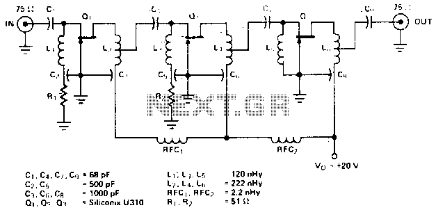
The amplifier circuit is designed for a 225 MHz center frequency, with a 1 dB bandwidth of 50 MHz, low input VSWR in a 75-ohm system, and a gain of 24 dB. Three stages of U310 FETs are utilized in...
Output-stage-power-booster
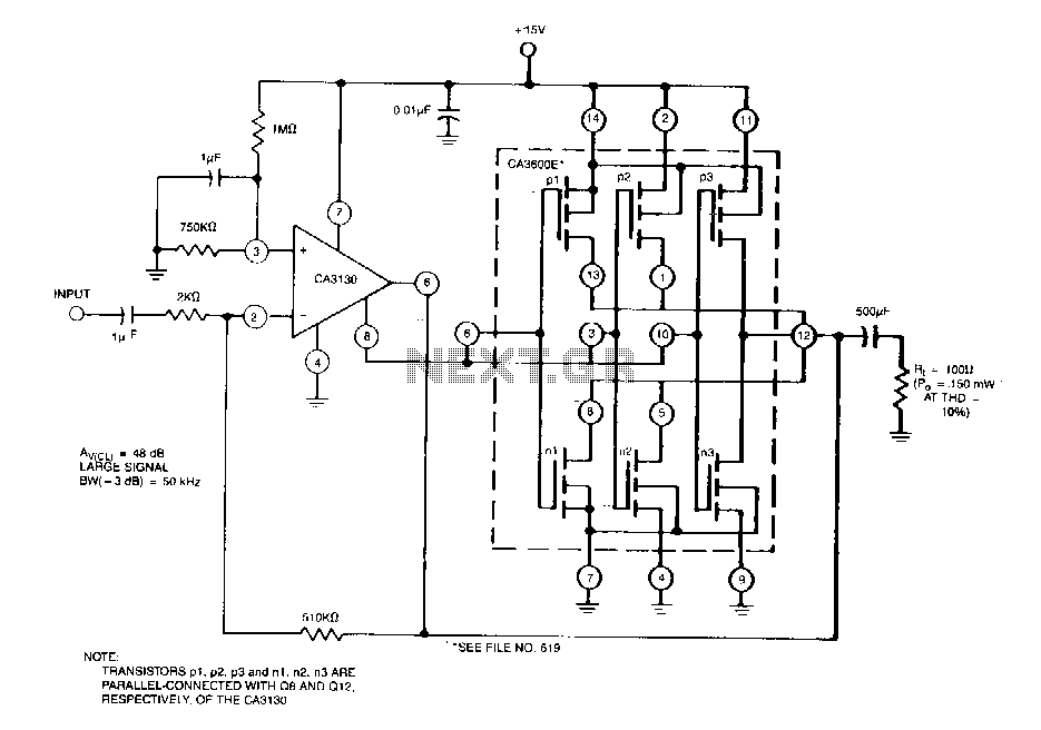
This circuit effectively enhances the current-sourcing and current-sinking capabilities of the CA3130 BiMOS operational amplifier. This configuration increases the current-handling capacity of the CA3130 output stage by approximately 2.5 times.
The circuit described is designed to augment the output performance of...

175MHz high-frequency amplifier circuit composed by a field effect transistor
A 175 MHz high-frequency amplifier circuit utilizing a field-effect transistor (FET) is presented. The field-effect transistor used is the 3D04H, along with its associated components and parameters.
The 175 MHz high-frequency amplifier circuit is designed to amplify signals in the specified...

High-frequency crystal oscillator
A high-speed oscillator can be created by integrating an MECL 10 crystal oscillator with an MECL III frequency doubler. One section of the MC10101 is configured as a 100 MHz crystal oscillator, with the crystal placed in series within the...

Instrumentation amplifier
Instrumentation amplifiers, also known as differential amplifiers, are specifically engineered to extract and amplify small differential signals from significantly larger common mode voltages. For use as building blocks within instrumentation amplifiers, operational amplifiers (op amps) must exhibit very low offset...
Wideband uhf amplifier with high-performance fets
The amplifier circuit is designed for a center frequency of 225 MHz, with a bandwidth of 50 MHz at 1 dB, low input voltage standing wave ratio (VSWR) in a 75-ohm system, and a gain of 24 dB. Three stages...

Wideband Active Small Magnetic Loop Antenna
There are extremely wideband software-defined radios (SDR) where a wideband antenna is a natural choice. Wideband small magnetic loops (WSM loops) have been used for 3-4 decades, and their effectiveness as a wideband SDR input is under evaluation. The WSM...

Extended common mode range of the instrumentation amplifier (INA101) circuit
This document describes the extended common mode input voltage range of an instrument amplifier circuit. The circuit consists of three precision instrument amplifiers, A1, A2, and A3, which can be INA101 or INA102 models. The figure illustrates that A1, A2,...