


XTR106 no external transistor circuit diagram of work
#XTR106
#transistor
#circuit diagram
#resistor
#simplified circuit
#emitter
#operational amplifier
#signal conditioning
#current loop
#industrial
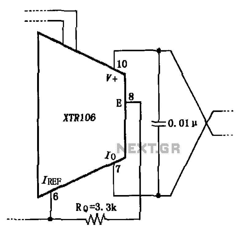
Description: The circuit has been simplified due to the cancellation of an external transistor. The connection between the emitter terminals of the original external transistor and a 3.3k resistor will be removed, as this change has led to a decrease in the accuracy of the internal power circuit.
The circuit modification involves the removal of an external transistor, which serves to streamline the design and potentially enhance reliability. The original configuration included a connection between the emitter terminals of the external transistor and a 3.3k resistor. This resistor typically functions to limit the current flowing through the transistor, ensuring that the device operates within safe parameters. However, the decision to eliminate this connection is based on the observed decline in the accuracy of the internal power circuit, which may have been influenced by the additional loading introduced by the external transistor and resistor.
In the revised circuit, attention must be given to maintaining the stability and performance of the internal power supply. It is essential to ensure that the remaining components can handle the required load without the external transistor's assistance. This may involve recalibrating the internal circuitry to accommodate the changes. Furthermore, the implications of removing the 3.3k resistor should be assessed to prevent excessive current that could lead to overheating or damage to the internal components.
Overall, the simplification of the circuit aims to enhance performance while addressing the issues related to accuracy in the power supply. Future testing and validation will be necessary to confirm the effectiveness of this modification and to ensure that the circuit meets the desired specifications. As shown, the circuit is canceled due to an external transistor becomes simplified. The connection between both original external transistor emitter feet and legs a 3.3k resist or. However, this connection will be leaving because the internal power circuit accuracy decreased.
The circuit modification involves the removal of an external transistor, which serves to streamline the design and potentially enhance reliability. The original configuration included a connection between the emitter terminals of the external transistor and a 3.3k resistor. This resistor typically functions to limit the current flowing through the transistor, ensuring that the device operates within safe parameters. However, the decision to eliminate this connection is based on the observed decline in the accuracy of the internal power circuit, which may have been influenced by the additional loading introduced by the external transistor and resistor.
In the revised circuit, attention must be given to maintaining the stability and performance of the internal power supply. It is essential to ensure that the remaining components can handle the required load without the external transistor's assistance. This may involve recalibrating the internal circuitry to accommodate the changes. Furthermore, the implications of removing the 3.3k resistor should be assessed to prevent excessive current that could lead to overheating or damage to the internal components.
Overall, the simplification of the circuit aims to enhance performance while addressing the issues related to accuracy in the power supply. Future testing and validation will be necessary to confirm the effectiveness of this modification and to ensure that the circuit meets the desired specifications. As shown, the circuit is canceled due to an external transistor becomes simplified. The connection between both original external transistor emitter feet and legs a 3.3k resist or. However, this connection will be leaving because the internal power circuit accuracy decreased.

transistors Role of capacitor in this circuit
Oscillation is expected at the resonant frequency where the positive feedback is in phase with the input, specifically at 0 degrees. For oscillation to take place, the gain must be equal to or greater than 1 at that frequency. There...

2 watt amplifier schematic diagram
The circuit is intentionally designed using older type transistors to achieve harmonic distortion and to mitigate the challenges of sourcing high-quality components. The amplifiers can be easily powered by a plug-in wall transformer rated at 12V. When SW1 is closed,...

A delay circuit using an operational amplifier
A delay circuit utilizing an operational amplifier functions as a comparator, providing high timing accuracy. The timer's delay range is from 1 to 30 seconds. The delay time is determined by resistors Ri, RP, and capacitor C. By adjusting RP,...
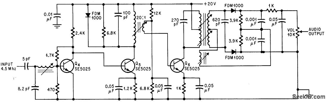
SOUND I F FOR COLOR TV
Utilizes three transistor stages and a Foster-Seeley discriminator to produce an audio output of 1 V peak-to-peak. -D. Bray, Solid State Makes Debut in Big Screen Color TV, Electronics, 39:8, p 99-105.
The circuit in question employs a combination of three...

Computer-Controlled 4-20mA Current Loop
In certain industries, a computer-controlled 4-20 mA current loop is utilized to manage various equipment. This current loop is employed to transmit a signal over a distance.
The 4-20 mA current loop is a standard method for transmitting analog signals in...

Miniature Loop Alarm
Simple construction, reliable operation, very small power consumption, and, most of all, small size. I started with CMOS logic gates, but was soon forced to abandon the concept after a few unsuccessful (and far too complicated) attempts. Then I suddenly...

Long-Duration Time Delay
Transistor Q1 and resistors R1, R2, and R3 form a constant current source, with the charge current adjustable to as low as a few nanoamperes. This current is insufficient to activate the UJT, where IP is 0.2 A, unless a...

The triangular wave carrier generator circuit diagram
The triangular wave circuit consists of two operational amplifiers (OPs). R62 serves as the offset adjustment, while R27 is utilized for peak adjustment. A switch is included to select different resistances, allowing for the generation of triangular waves at varying...

Transistor common emitter amplifier circuit
The circuit is a bias circuit for automatic stabilizers that maintains a stable quiescent operating point with good thermal stability. It utilizes a three-pole tube with an NPN type transistor, characterized by a small Iceo. An adjustment potentiometer, RP, is...