


XTR110 expand the drive current circuit diagram
#XTR110
#current expansion
#NPN transistor
#voltage reference
#drive current
#circuit diagram
#external transistor
#40V
#output current
#amplifier

Description: The XTR110 features an internal voltage reference that can output a current of 10mA. By incorporating an external NPN transistor, designated as QREF, the output current capability can be increased. When the VCC voltage reaches 40V, a 2N3055 transistor can be utilized to further extend the output current capacity up to 100mA.
The XTR110 is a precision current loop transmitter that is commonly used in industrial applications for converting voltage signals into current signals. The internal voltage reference of the XTR110 provides a stable reference point, allowing for consistent performance across various operating conditions. The output current of 10mA is suitable for many applications; however, in scenarios where higher current output is required, the addition of an external NPN transistor, such as the 2N3055, is advantageous.
The 2N3055 is a power transistor capable of handling higher currents and voltages, making it an ideal choice for this application. By connecting the 2N3055 to the output of the XTR110, the current output can be increased significantly, allowing the circuit to drive larger loads or longer cable runs without signal degradation. This configuration is particularly useful in applications where the load impedance may vary or where additional current is necessary for proper operation.
To implement this enhancement, the base of the 2N3055 should be connected to the output of the XTR110, while the collector is connected to the load. The emitter of the 2N3055 will provide the increased current output. It is essential to ensure that the power supply voltage (VCC) does not exceed the maximum rating of the 2N3055, which can handle up to 40V, to prevent damage to the transistor.
This setup allows for flexible design options in current loop applications, providing the ability to scale the output current based on specific requirements while maintaining the precision and stability of the XTR110's voltage reference. Proper heat sinking should also be considered for the 2N3055 to ensure reliable operation under higher current conditions. As shown in FIG, XTR110 internal voltage reference output current of 10mA, add an external NPN transistor QREF can expand the output current. When VCC rises to 40V, the transis tor QREF taken as 2N3055, can expand the output current (up to 100mA).
The XTR110 is a precision current loop transmitter that is commonly used in industrial applications for converting voltage signals into current signals. The internal voltage reference of the XTR110 provides a stable reference point, allowing for consistent performance across various operating conditions. The output current of 10mA is suitable for many applications; however, in scenarios where higher current output is required, the addition of an external NPN transistor, such as the 2N3055, is advantageous.
The 2N3055 is a power transistor capable of handling higher currents and voltages, making it an ideal choice for this application. By connecting the 2N3055 to the output of the XTR110, the current output can be increased significantly, allowing the circuit to drive larger loads or longer cable runs without signal degradation. This configuration is particularly useful in applications where the load impedance may vary or where additional current is necessary for proper operation.
To implement this enhancement, the base of the 2N3055 should be connected to the output of the XTR110, while the collector is connected to the load. The emitter of the 2N3055 will provide the increased current output. It is essential to ensure that the power supply voltage (VCC) does not exceed the maximum rating of the 2N3055, which can handle up to 40V, to prevent damage to the transistor.
This setup allows for flexible design options in current loop applications, providing the ability to scale the output current based on specific requirements while maintaining the precision and stability of the XTR110's voltage reference. Proper heat sinking should also be considered for the 2N3055 to ensure reliable operation under higher current conditions. As shown in FIG, XTR110 internal voltage reference output current of 10mA, add an external NPN transistor QREF can expand the output current. When VCC rises to 40V, the transis tor QREF taken as 2N3055, can expand the output current (up to 100mA).
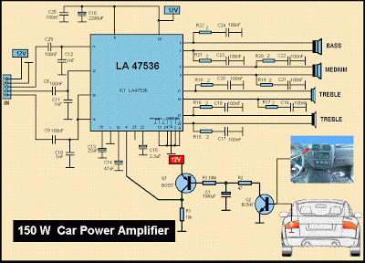
Schematic MP3 Car Audio Power AmplifierCircuits
This is a diagram of a car audio active loudspeaker utilizing the LF353 operational amplifier from National Semiconductor. For optimal performance, the NE5532 is recommended to split the audio signal into three frequency bands using an active filter. The SANYO...

KA9270 Audio Filter Introduction
KGA8010 is a broadband distributed amplifier utilizing 0.1 um-gate GaAs P-HEMT and coplanar waveguide technologies. The KGA8010 can serve as a multi-purpose amplifier for 40 Gb/s optical communication and millimeter wave applications. Manufactured by Oki Semiconductor.
The KGA8010 broadband distributed amplifier...

XTR101 bridge input voltage excitation circuit diagram
The circuit utilizes the LM129 voltage regulator to produce a 6.9V voltage reference, supplying a current of 1.0147mA from the 6.9V reference voltage to the bridge. The bridge may consist of varistor-type pressure sensors.
The LM129 voltage regulator is a precision...
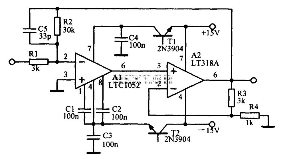
A circuit diagram of an amplifier circuit to enhance the output current and voltage
Amplifying circuit diagram to enhance the output current and voltage.
An amplifying circuit is designed to increase the amplitude of an input signal, resulting in a higher output current and voltage. This type of circuit is commonly utilized in various electronic...

Amplifier Compressor MC3340P
The output is rectified, and TR2 controls the gain of the ICL. This audio compressor circuit uses an MC3340P as a variable gain amplifier.
The audio compressor circuit described utilizes an MC3340P integrated circuit, which functions as a variable gain amplifier...

Digitally-controlled-voltage-reference
This circuit demonstrates a straightforward approach to achieving a voltage reference that can be adjusted using an 8-bit Digital-to-Analog Converter (DAC) equipped with an integrated voltage reference. The analog output from the DAC controls the trim pin of the ZNREF025...

Bird Feeder Monitor Circuit
The first amplifier circuit is a bird phone. In this circuit, the electret microphone (MIC1) is mounted in the neck of a large plastic funnel. The amplifier, built around an MC34119, is then placed outside of the funnel with the...

audio amp
Install the red LED at D2. Align the flat side of the LED with the PCB outline. Install a jumper wire at R4 and install a 220µF electrolytic capacitor at C8 with the negative side connected to ground. Connect pin...

Power Supply for Amlifiers [B]
Proposed power supply for amplifier 100W v-mosfet is what appears in the above form. It has separated supply for the various stages of supply, stage for power, stage for control, supply for preamplifier and for stage of protection. Whoever wants...