



Wideband two-pole high-pass filter
The circuit provides a 10MHz cutoff frequency. Resistor R3 ensures that the input capacitance of the amplifier does not interact with the filter response at the...

Variable filter
The filter produces three outputs: high-pass, bandpass, and low-pass. Frequency is linearly proportional to the gain of the two integrators. Two CA3080's, (IC2,...

Universal active filter
The circuit as shown gives the bandpass operation the transfer function calculated from FBP(s) = where = 1 + s/Qo>0 + s2/w02. The cut-off frequency, 0, and the...

Fiberoptic interface
An op amp is used to interface between a fiberoptic system and the MOS SCR to multi-cycle, half-wave control of a load. This receiver has two complementary outp...

Jfet ac coupled integrator
This circuit utilizes the "µ-amp" technique to achieve very high voltage gain. Using CI in the circuit as a Miller integrator, or capacitance multiplier, all...

Simulated inductor
With a constant current excitation, the voltage dropped across an inductance increases with frequency. Thus, an active device whose output increases with freque...

High output 600 Ohm line driver
The circuit has a "floating" output, i.e., it behaves like an isolated transformer winding, with the output amplitude remaining unchanged whether the center or ...
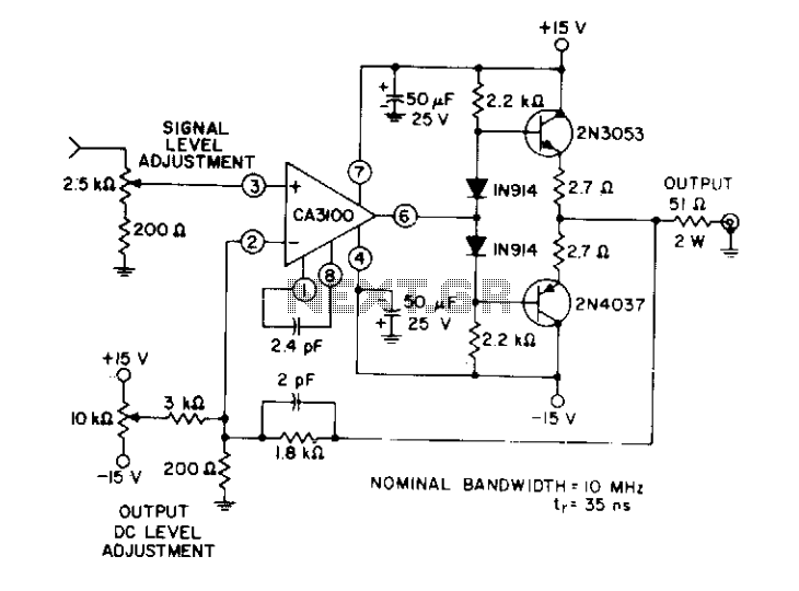
50Ohm transmission line driver
This circuit uses a wideband, high slew rate CA3100 BiMOS.op amp. The slew rate for this amplifier is 28 V//as.
...

Line driver provides full rail excursions
The logic input is applied to opto-isolators Ul and U2 with, respectively, npn and pnp emitter follower outputs. Dc balance is adjusted by potentiometer R2. The...
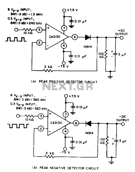
Peak detector
Circuits are easily implemented using the CA3130 BiMOS op amp. For large-signal inputs the bandwidth of the peak-negative circuit is less than that of the peak-...

Zero-crossing detector
This zero-crossing detector uses a dual LM393 comparator, and easily controls hysteresis by the reference levels which are set on the comparator inputs. The cir...

Electrometer amplifier with overload protection
The preamplifier is protected from excessive input signals of either polarity by the 2N5909 junction field-effect transistor. A nulling circuit makes it possibl...

Photodiode current-to-voltage converter
The circuit uses three CA3130 BiMOS op amps in an application sensitive to sub-picoampere input currents....

Precision peak-to-peak ac-dc converter
Using a CA3140 BiMOS op amp and a single positive supply converts a conventional voltage doubler with two precision diodes into a precision peak-to-peak ac-to-d...

Voltage-to-current converters
A simple voltage-to-current converter is shown in the figure. The current out is 0t or Vjn/R. For negative currents, a pnp can be used and, for better accuracy,...

Buffered breakout box
The monitoring circuit consists of four tri-color LEDs driven by an equal number of op amps configured as gain-of-one inverting amplifiers. Each LED is wired in...

Schmitt trigger comparator
The comparator has an output pull-up resistor RL and is connected up to operate as a Schmitt trigger using the single rail supply Vcc. The feedback resistors Rl...
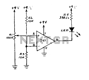
Demo comparator
This circuit is an op amp without a feedback resistor. R2 and R3 junction point sets the reference voltage. When the input voltage set by Rl is below the refere...

High input comparator
The circuit uses both halves of the CA3290 BiMOS dual voltage comparator. The LED will be turned "ON" whenever the input signal is above the lower limit (VL) bu...

Hi-Low level comparator
The voltage to be compared is fed through diode Dl and D2 to the voltage dividers Rl and R5 where the low and high limits are present. When the voltage level of...