


16 Step Analog Sequencer circuit
#analog sequencer
#CMOS
#4067n multiplexer
#DIY
#sn76477
#tempo control
#indicator lights
#music synthesis
#electronic music
#test circuit

Description: The following video showcases a test circuit of a 16-step analog sequencer based on Mauno Tuominen's schematic for an analog CMOS sequencer utilizing a 4067N multiplexer/demultiplexer. A DIY version of the sequencer can be found at studiomanus.com. An old SN76477 was repurposed for this project, starting with basic components such as indicator lights, tempo control, and a simple oscillator. The ultimate goal is to develop a comprehensive 16-step sequencer/synthesizer based on the SN76477, enabling extensive sound shaping for each step in the sequence. Although the current cost of the sequencer is under $100, the final version will likely exceed this budget, but the anticipated results are expected to be significant. The initial test circuit may not produce the most musical sounds at this stage, but its functionality and straightforward design are the primary focus. The design has been enhanced with a simple 555 timer for clock generation and the capability to control the number of steps in the sequence using a 4063N. This aspect has yet to be tested and remains on the agenda. Feedback from individuals experienced with these components and circuit design is welcomed.
The described analog sequencer circuit utilizes a 4067N multiplexer/demultiplexer, which serves as the core component to manage the signal routing for each step in the sequence. The 16-step sequencer operates by sequentially activating each step based on a clock signal generated by a 555 timer. The 555 timer is configured in astable mode, producing a continuous square wave output that serves as the timing reference for the sequencer. This clock signal determines the rate at which the sequencer advances through its steps.
Each step in the sequencer can be associated with various sound-shaping parameters, which can be manipulated to create unique audio outputs. The SN76477 chip is particularly suited for this purpose, as it is a versatile sound generator capable of producing a range of tones and effects. The integration of the 4063N allows for dynamic control over the number of active steps in the sequence, providing flexibility in performance and composition.
The circuit design incorporates indicator lights to provide visual feedback on the active step, enhancing user interaction. The current iteration primarily focuses on the basic functionality of the sequencer, with further refinements planned to improve the musicality and complexity of the output. The final implementation is expected to include additional features such as variable step lengths, different waveforms, and modulation options, significantly expanding the creative possibilities for sound design.
As the project progresses, thorough testing and evaluation of each component's performance will be essential for ensuring reliability and achieving the desired sound quality. Collaboration and feedback from experienced circuit designers will be invaluable in refining the design and addressing any challenges encountered during the development process.The following video is of my test circuit of a 16 step analog sequencer based on Mauno Tuominen`s schematic for an analog CMOS sequencer based around at 4067n multiplexer/demultiplexer. You can see a DIY version of the sequencer here at studiomanus. com. I had an old sn76477 which I had been planning on turning into something so I started with the basics indicator lights, tempo, and a simple oscillator.
The eventual plan is to expand this out into a large 16 step sequencer/synth based around the sn76477 allowing for extensive sound shaping of each step in the sequence. Although the sequencer is well under $100 by the time this is completely finished it will likely cost well over that but the result should be substantial.
In the meantime, take a gander at the initial test circuit. The sounds aren`t the most musical at this time, but it`s function and simple design is more the point. I`ve expanded on the original design using a simple 555 timer for the clock and the ability to control the number of steps in the sequence through use of the 4063N.
This has not been tested that`s on my to do list. If anyone who reads this is well versed in these components and circuit design I`d love to hear feedback.
The described analog sequencer circuit utilizes a 4067N multiplexer/demultiplexer, which serves as the core component to manage the signal routing for each step in the sequence. The 16-step sequencer operates by sequentially activating each step based on a clock signal generated by a 555 timer. The 555 timer is configured in astable mode, producing a continuous square wave output that serves as the timing reference for the sequencer. This clock signal determines the rate at which the sequencer advances through its steps.
Each step in the sequencer can be associated with various sound-shaping parameters, which can be manipulated to create unique audio outputs. The SN76477 chip is particularly suited for this purpose, as it is a versatile sound generator capable of producing a range of tones and effects. The integration of the 4063N allows for dynamic control over the number of active steps in the sequence, providing flexibility in performance and composition.
The circuit design incorporates indicator lights to provide visual feedback on the active step, enhancing user interaction. The current iteration primarily focuses on the basic functionality of the sequencer, with further refinements planned to improve the musicality and complexity of the output. The final implementation is expected to include additional features such as variable step lengths, different waveforms, and modulation options, significantly expanding the creative possibilities for sound design.
As the project progresses, thorough testing and evaluation of each component's performance will be essential for ensuring reliability and achieving the desired sound quality. Collaboration and feedback from experienced circuit designers will be invaluable in refining the design and addressing any challenges encountered during the development process.The following video is of my test circuit of a 16 step analog sequencer based on Mauno Tuominen`s schematic for an analog CMOS sequencer based around at 4067n multiplexer/demultiplexer. You can see a DIY version of the sequencer here at studiomanus. com. I had an old sn76477 which I had been planning on turning into something so I started with the basics indicator lights, tempo, and a simple oscillator.
The eventual plan is to expand this out into a large 16 step sequencer/synth based around the sn76477 allowing for extensive sound shaping of each step in the sequence. Although the sequencer is well under $100 by the time this is completely finished it will likely cost well over that but the result should be substantial.
In the meantime, take a gander at the initial test circuit. The sounds aren`t the most musical at this time, but it`s function and simple design is more the point. I`ve expanded on the original design using a simple 555 timer for the clock and the ability to control the number of steps in the sequence through use of the 4063N.
This has not been tested that`s on my to do list. If anyone who reads this is well versed in these components and circuit design I`d love to hear feedback.

5 Minute Signal
For the past year and a half, a group based in Ann Arbor, Michigan, named GO-Tech has been formed, uniting individuals interested in creating projects using technology, such as hardware, software, metal, and wood. This initiative is referred to as...

Digital integrated circuits using CMOS circuit Responder
A digital integrated circuit simplifies the response process significantly. The diagram illustrates a circuit comprising four responder groups.
The digital integrated circuit described serves as a crucial component in various electronic systems, primarily focusing on enhancing response efficiency. It comprises four...
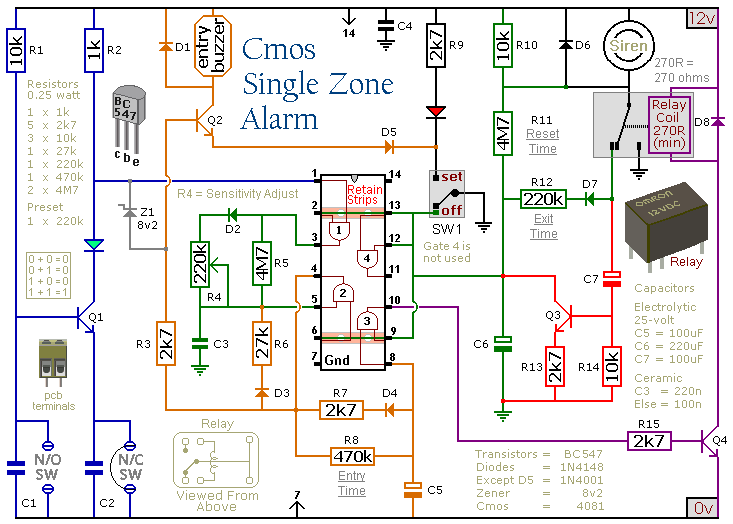
cmos based single zone alarm
This circuit includes automatic exit and entry delays, a timed bell cut-off, and a system reset feature. It is designed to support both normally-open and normally-closed switches and can accommodate standard input devices such as pressure mats, magnetic reed contacts,...

Cmos 555 astable generates square waves
A CMOS timer generates true square waves because, unlike the bipolar 555, its output swings from rail to rail. The component values shown give a frequency of about 400 Hz.
The CMOS timer circuit operates by utilizing complementary metal-oxide-semiconductor technology to...

Cmos-oscillator
The common clock oscillator illustrated in Fig. 68-19A has two minor issues: it may not oscillate if the transition regions of its two gates differ. If it does oscillate, it might occasionally operate at a slightly lower frequency than predicted...

1.5V liquid crystal display circuit
The Motorola company's MC14440 CMOS integrated circuit is designed for timing and displaying calendar functions. It utilizes a 32.768 kHz NT cutting type quartz crystal along with fine-tune capacitance to generate time-based signals. The display circuit operates on a 1.5...

Cmos touch switch
This touch switch does not rely on mains hum for switching; it can be used with battery-powered circuits. The Schmitt trigger IC1 forms a 100 kHz oscillator, and IC2a, which is biased into the linear region, amplifies the output and...

MePADS
If you are considering building the Desert Ratt 2, it is advisable to read all the accompanying text, as it contains relevant construction details. Engaging with the comments and replies can also provide additional insights, as previous blog posts have...

Logic Probe Project
CMOS logic integrated circuits are highly versatile devices commonly utilized in modern electronic circuits. Testing these circuits with a standard multi-meter can be challenging due to the involvement of both static and pulsing voltages. A voltage reading of half the...