


20 MHz VHF CRYSTAL OSCILLATOR
#20 MHz
#VHF
#crystal oscillator
#third harmonic
#diode clamp
#transistor
#linear mode
#constant amplitude

Description: A typical circuit operating at 20 MHz is presented. The crystal, which possesses an internal series resistance (RS) of 14 ohms, oscillates at its third harmonic. Diode clamps D1 and D2 provide constant amplitude control. The transistor functions continuously in a linear mode throughout the entire oscillation cycle, reflecting a reasonably constant load across the crystal at all times.
This circuit operates at a frequency of 20 MHz, utilizing a crystal oscillator that is tuned to its third harmonic. The crystal's internal series resistance (RS) of 14 ohms plays a critical role in determining the quality factor and stability of the oscillation. The harmonic oscillation allows for efficient signal generation, making it suitable for various applications in communication systems.
The inclusion of diode clamps D1 and D2 serves to regulate the amplitude of the oscillations, ensuring that the output signal remains within a defined voltage range. This is particularly important in preventing signal distortion and maintaining the integrity of the waveform during operation. These diodes work by clipping the peaks of the oscillation, thereby providing a form of amplitude stabilization.
The transistor in this circuit is designed to operate in a linear mode, allowing it to amplify the oscillating signal without introducing significant distortion. By maintaining a continuous operation throughout the oscillation cycle, the transistor helps to ensure that the load presented to the crystal remains relatively constant. This consistent load is crucial for sustaining the oscillation and achieving stable frequency output.
Overall, the circuit exemplifies the principles of harmonic oscillation, amplitude control, and linear amplification, making it a robust solution for frequency generation at 20 MHz. The careful selection of components, including the crystal, diodes, and transistor, is essential for optimizing performance and ensuring reliability in practical applications.A typical circuit at 20 MHz is shown. The crystal, which has an internal series resistance RS, of 14 ©, oscillates at its third harmonic. The diode clamp D1 and D2 provides a constant amplitude control. The transistor operates continuously in a linear mode over a complete cycle of oscillation, and reflects a reasonably constant load across the c rystal at an times.
This circuit operates at a frequency of 20 MHz, utilizing a crystal oscillator that is tuned to its third harmonic. The crystal's internal series resistance (RS) of 14 ohms plays a critical role in determining the quality factor and stability of the oscillation. The harmonic oscillation allows for efficient signal generation, making it suitable for various applications in communication systems.
The inclusion of diode clamps D1 and D2 serves to regulate the amplitude of the oscillations, ensuring that the output signal remains within a defined voltage range. This is particularly important in preventing signal distortion and maintaining the integrity of the waveform during operation. These diodes work by clipping the peaks of the oscillation, thereby providing a form of amplitude stabilization.
The transistor in this circuit is designed to operate in a linear mode, allowing it to amplify the oscillating signal without introducing significant distortion. By maintaining a continuous operation throughout the oscillation cycle, the transistor helps to ensure that the load presented to the crystal remains relatively constant. This consistent load is crucial for sustaining the oscillation and achieving stable frequency output.
Overall, the circuit exemplifies the principles of harmonic oscillation, amplitude control, and linear amplification, making it a robust solution for frequency generation at 20 MHz. The careful selection of components, including the crystal, diodes, and transistor, is essential for optimizing performance and ensuring reliability in practical applications.A typical circuit at 20 MHz is shown. The crystal, which has an internal series resistance RS, of 14 ©, oscillates at its third harmonic. The diode clamp D1 and D2 provides a constant amplitude control. The transistor operates continuously in a linear mode over a complete cycle of oscillation, and reflects a reasonably constant load across the c rystal at an times.
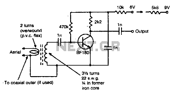
Vhf preamplifier
This simple circuit provides a gain of 15 dB and can be mounted on a 1 inch by 2 inch PCB. Coil specifications are provided for a frequency range of 85 to 95 MHz. For other frequencies, the coil should...

Schematics VHF FM Receiver TDA7000 88-108 MHz
The 10K resistor is necessary if the receiver is to mute (squelch) under no-signal conditions. An additional 100K resistor can be added in series with this resistor to create an adjustable squelch. This circuit is designed to drive a crystal...
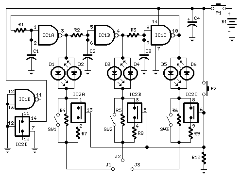
Transistor Pin Identifier
Tests transistors and diodes for polarity. A three-phase waveform is derived from the 350Hz ring-of-three oscillator formed by IC1A, IC1B, and IC1C, and applied to the device under test via the LEDs. The oscillator waveform enables each pair of device...

MAX2606 VHF FM Transmitter
To test VHF receivers independently from local radio stations, a frequency-modulated oscillator is required, covering the range of 89.5 to 108 MHz. Building such an oscillator with discrete components is challenging. The MAX260x series from Maxim offers five integrated oscillator...

1 transistor treasure locator circuit
The locator utilizes a transistor radio as the detector. By tuning the radio to a weak station, the capacitor C1 can be adjusted so that the locator's oscillator beats against the received signal. When the search head passes over metal,...

Flasher Circuits
The basic two-transistor flasher has become widely utilized in various applications due to its simplicity and versatility. It has been employed in circuits such as a micropower low battery indicator, a lightning detector, an off-line switching power supply, a micropower...
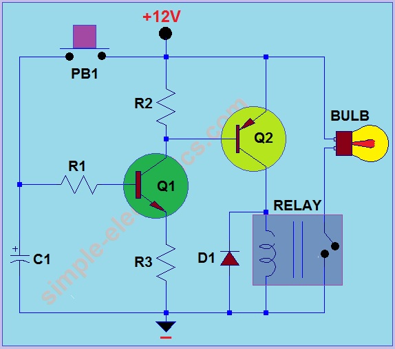
Car Headlight with Delay Circuit
This circuit operates by activating a headlight when the push-button PB1 is pressed. The headlight remains illuminated for a predetermined duration, which can range from several seconds to minutes, before automatically turning off. When PB1 is engaged, capacitor C1 begins...

Simple VHF FM radio
The RF stage of the receiver utilizes a transistor VT1, functioning as both a mixer and a local oscillator while also serving as a synchronous detector. A headphone cable acts as an antenna, capturing signals that are directed to the...

GE/MACOM MASTR-III VHF Station
This article provides conversion instructions for radio model GE/MACOM MASTR-III Group 2 (150.8-174 MHz) Repeater or Base, Combination Number SXS, to enable it to operate effectively in the 144-148 MHz range. It is important to note that this document is...