


20Mhz-vhf-crystal-oscillator
#20MHz
#VHF
#crystal oscillator
#third harmonic
#diode clamp
#constant amplitude
#electronic circuit
#frequency generation

Description: A typical circuit operating at 20 MHz is illustrated. The crystal, featuring an internal series resistance (Rs) of 14 ohms, oscillates at its third harmonic frequency. Diode clamps D1 and D2 ensure constant amplitude control. The transistor functions continuously in a linear mode throughout the entire oscillation cycle, maintaining a relatively constant load across the crystal at all times.
The circuit operates at a frequency of 20 MHz, utilizing a crystal oscillator that is specifically designed to resonate at its third harmonic. The crystal's internal series resistance of 14 ohms plays a critical role in determining the quality factor (Q) of the oscillator, influencing the stability and purity of the output frequency. This feature is essential for applications requiring precise frequency control.
In this configuration, diode clamps D1 and D2 are employed to regulate the amplitude of the oscillation. By limiting the peak voltage across the crystal, these diodes prevent distortion and ensure that the oscillation remains within the desired amplitude range. This constant amplitude control is vital for maintaining consistent performance and preventing potential damage to the crystal due to excessive voltage.
The transistor's role in this circuit is to operate in a linear mode, allowing it to amplify the oscillation signal effectively. By functioning continuously throughout the entire cycle of oscillation, the transistor provides the necessary gain to sustain the oscillation while reflecting a constant load across the crystal. This characteristic is crucial for maintaining the oscillator's stability and minimizing frequency drift.
Overall, the combination of the crystal's specific series resistance, the diode clamps for amplitude control, and the linear operation of the transistor creates a reliable and stable oscillator circuit suitable for various electronic applications. The design ensures that the circuit can deliver a consistent output frequency while maintaining the integrity of the oscillation waveform.A typical circuit at 20 MHz is shown. The crystal, which has an internal series resistance Rs of 14ohm, oscillates at its third harmonic. The diode clamp Dl and D2 provides a constant amplitude control. The transistor operates continuously in a linear mode over a complete cycle of oscillation, and reflects a reasonably constant load across the crystal at all times.
The circuit operates at a frequency of 20 MHz, utilizing a crystal oscillator that is specifically designed to resonate at its third harmonic. The crystal's internal series resistance of 14 ohms plays a critical role in determining the quality factor (Q) of the oscillator, influencing the stability and purity of the output frequency. This feature is essential for applications requiring precise frequency control.
In this configuration, diode clamps D1 and D2 are employed to regulate the amplitude of the oscillation. By limiting the peak voltage across the crystal, these diodes prevent distortion and ensure that the oscillation remains within the desired amplitude range. This constant amplitude control is vital for maintaining consistent performance and preventing potential damage to the crystal due to excessive voltage.
The transistor's role in this circuit is to operate in a linear mode, allowing it to amplify the oscillation signal effectively. By functioning continuously throughout the entire cycle of oscillation, the transistor provides the necessary gain to sustain the oscillation while reflecting a constant load across the crystal. This characteristic is crucial for maintaining the oscillator's stability and minimizing frequency drift.
Overall, the combination of the crystal's specific series resistance, the diode clamps for amplitude control, and the linear operation of the transistor creates a reliable and stable oscillator circuit suitable for various electronic applications. The design ensures that the circuit can deliver a consistent output frequency while maintaining the integrity of the oscillation waveform.A typical circuit at 20 MHz is shown. The crystal, which has an internal series resistance Rs of 14ohm, oscillates at its third harmonic. The diode clamp Dl and D2 provides a constant amplitude control. The transistor operates continuously in a linear mode over a complete cycle of oscillation, and reflects a reasonably constant load across the crystal at all times.

Crystal Controlled Oscillator Circuit
Crystal Controlled Oscillator Circuit. This general-purpose signal source is highly effective in signal-tracing applications. The output level is adjustable.
The crystal-controlled oscillator circuit is designed to provide a stable and precise frequency output, which is essential for various electronic applications, particularly...
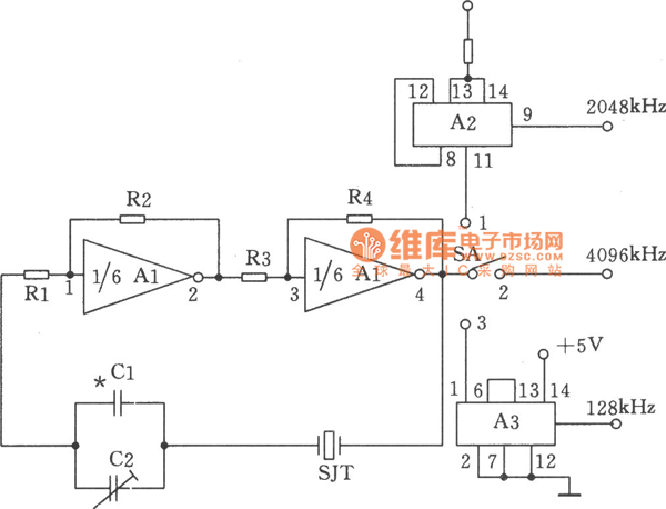
Mutiple Output Crystal Oscillator Sensor
The figure illustrates a multiple output crystal oscillator, which primarily consists of three gates of Al, four resistors, two capacitors, and a crystal. Resistors R1 to R4 offset two inverters within the linear range and are connected between pin 4...

VHF FM Antenna Booster Circuit
This high-performance two-stage antenna amplifier for the VHF FM broadcast band, when paired with a quality directional antenna, allows for the reception of distant (DX) stations. It significantly enhances the reception of FM signals that may otherwise be considered marginal...

Temperature-compensated crystal oscillator
Two different negative-coefficient capacitors are blended to produce the desired change in capacitance to counteract or compensate for the decrease in frequency of the "normal" AT-cut characteristics.
The circuit utilizes a combination of two negative-coefficient capacitors to achieve a specific capacitance...

VHF field strength meter
This is a simple and low-cost wideband VHF field strength meter. The field strength is measured by converting the radio signal to DC and measuring it. The RF signal is picked up by the coil and rectified by the diode...

1024KHz temperature compensation crystal oscillator circuit diagram
This circuit is a 1024 kHz temperature-compensated crystal oscillator. The circuit theory is illustrated. Due to the low output signal level of the circuit, a buffer using the following transistor VT1 is implemented for amplification. The base bias resistor R2,...

Easy-start-up-crystal-oscillator
This low-cost, crystal-controlled oscillator employs a single TTL gate. Two key factors facilitate the oscillator's start-up: the configuration of NAND gates G1, G2, and G3 in an unstable logic state, and the high loop gain provided by the three inverters....

marker generator
A resistor of 100K Ohm is connected between pin 10 and pin 11, while another resistor of 2K Ohm is present in the circuit. The fixed capacitor was determined through trial and error to achieve resonance with the crystal at...

VHF super-regenerative receiver circuit
The image illustrates the JFET VHF band super-regenerative receiver circuit. It features high discharge tubes V1 and V2, which serve as the super-regenerative detector tubes. IC1 functions as a low-frequency amplifier. The circuit exhibits a sensitivity of better than 1...