


32.768 KHz Oscillator using Watch Crystal
#32.768 KHz
#watch crystal
#square wave
#binary counter
#4069 inverter
#frequency
#timer
#digital logic

Description: This weblog focuses on electronic circuit schematics, PCB design, DIY kits, and electronic project diagrams. It discusses a 32.768 kHz square wave generated by a common watch crystal. This output can be connected to a 15-stage binary counter to achieve a 1-second square wave. The circuit utilizing the 4069 inverter is preferred over the transistor circuit as it produces a superior waveform. The single transistor circuit yields a ramping waveform but has the advantage of swinging across the entire supply voltage range, allowing it to effectively drive the input to a CMOS binary counter.
The circuit described operates based on the oscillation of a 32.768 kHz crystal, a frequency commonly used in timekeeping applications due to its stability and accuracy. The crystal generates a precise square wave output, which is essential for timing applications. This output is then fed into a 15-stage binary counter, which divides the frequency down to a 1 Hz square wave, suitable for various timing applications.
The choice of the 4069 inverter is significant as it provides a clean and stable output waveform, which is critical for digital circuits that rely on precise timing signals. The inverter circuit enhances the signal integrity, reducing noise and distortion that could arise from alternative configurations, such as those using a single transistor.
The single transistor circuit, while capable of producing a square wave, tends to generate a ramping waveform. This characteristic may not be suitable for all applications, particularly where sharp transitions are required. However, its ability to swing the output across the full supply voltage range allows it to interface directly with CMOS binary counters, which typically require a full rail-to-rail signal for reliable operation.
Overall, the circuit design choices made in this application reflect a balance between waveform quality and operational requirements, ensuring that the generated square wave can effectively drive subsequent digital circuitry.Welcome to the weblog where we discuss about electronic circuits schematics, PCB design, diy kits and electronic projects diagrams. a 32. 768 KHz square wave from a common watch crystal. The output can be fed to a 15 stage binary counter to obtain a 1 second square wave. The circuit on the left using the 4069 inverter is recommended over the trans istor circuit and produces a better waveform. The single transistor circuit produces more of a ramping waveform but the output swings the full supply voltage range so it will easily drive the input to a CMOS binary counter.
The circuit described operates based on the oscillation of a 32.768 kHz crystal, a frequency commonly used in timekeeping applications due to its stability and accuracy. The crystal generates a precise square wave output, which is essential for timing applications. This output is then fed into a 15-stage binary counter, which divides the frequency down to a 1 Hz square wave, suitable for various timing applications.
The choice of the 4069 inverter is significant as it provides a clean and stable output waveform, which is critical for digital circuits that rely on precise timing signals. The inverter circuit enhances the signal integrity, reducing noise and distortion that could arise from alternative configurations, such as those using a single transistor.
The single transistor circuit, while capable of producing a square wave, tends to generate a ramping waveform. This characteristic may not be suitable for all applications, particularly where sharp transitions are required. However, its ability to swing the output across the full supply voltage range allows it to interface directly with CMOS binary counters, which typically require a full rail-to-rail signal for reliable operation.
Overall, the circuit design choices made in this application reflect a balance between waveform quality and operational requirements, ensuring that the generated square wave can effectively drive subsequent digital circuitry.Welcome to the weblog where we discuss about electronic circuits schematics, PCB design, diy kits and electronic projects diagrams. a 32. 768 KHz square wave from a common watch crystal. The output can be fed to a 15 stage binary counter to obtain a 1 second square wave. The circuit on the left using the 4069 inverter is recommended over the trans istor circuit and produces a better waveform. The single transistor circuit produces more of a ramping waveform but the output swings the full supply voltage range so it will easily drive the input to a CMOS binary counter.

headlights timer
This device is a simple timer that keeps the headlights of a vehicle illuminated for approximately 1 minute and 30 seconds. This feature is particularly useful when accessing dark areas, eliminating the need to return to manually switch off the...

A Very Useful Timed Beeper Circuit Schematic
This circuit is designed to provide alerts after a predetermined time interval. It is ideal for tabletop games that necessitate a fixed duration for answering questions or moving pieces. In this context, it serves as a contemporary alternative to the...

The switch shut off time delay circuit diagram
The switch shut-off time delay circuit consists of a timer, optocouplers, a bridge SCR, and an SCR AC switch. When the control button is released, it allows the motor or other AC power to remain active for one hour. Upon...

A Regularly Repeating Interval Timer
This circuit features an adjustable output timer capable of re-triggering at regular intervals. The output duration can range from a fraction of a second to half an hour or longer, with the ability to recur at intervals spanning from seconds...

Auto Light Time/ Dimmer
A light timer/dimmer, similar to those found in dome lights, is desired, but guidance on how to begin the project is needed.
A light timer/dimmer circuit is designed to control the brightness of a light source and to provide a timed...
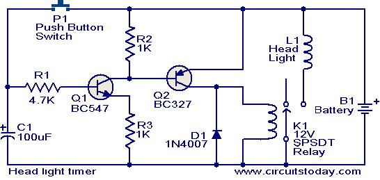
Head light timer circuit
This circuit is a compact timer that keeps the headlights of a car on for approximately 1.5 minutes before turning them off. Incorporating this circuit into a vehicle allows access to dark areas without the need to return and manually...

Timing within the one-chip computer Counter and interrupt system
This document will present an overview of two critical components within a one-chip computer: the timing/counter system and the interrupt system. Through this explanation, readers will gain insight into the operating principles of these systems. For illustration, consider an alarm...

Timer circuit
The schematic diagram is straightforward. SW1 is a pushbutton used to start the timer. The outputs are set to logic level 0 when the timer is inactive and to logic level 1 when the timer is triggered. The relay driver...
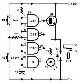
long delay timer schematics
This timer is designed to automatically switch off a portable radio after a set period, allowing users to relax without worrying about battery drain. Resistor R1 and capacitor C1 create a long time constant. When switch P2 is momentarily closed,...