


50/50% duty astable multivibrator circuit using IC 4047
#IC 4047
#astable multivibrator
#50/50 duty cycle
#frequency doubling
#LED indicator
#square wave
#timing circuit
#digital oscillator
#pulse generation
#signal frequency
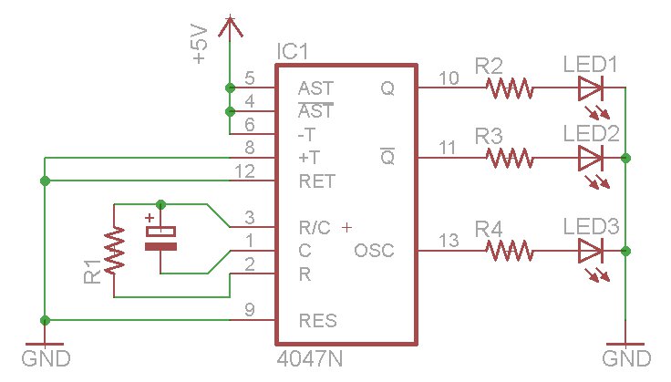
Description: The oscillator output generates a signal that is approximately twice the frequency of Q. The other pins will be considered subsequently. In a brief video demonstration, LEDs are connected to all three outputs, illustrating the alternating behavior of Q and Q, along with the increased frequency of the OSC output. This example showcases the astable mode of operation. The circuit diagram is provided below. A notable limitation of using a 4047 IC is that the duty cycle of the astable output cannot be modified; it remains consistently at 50% high and 50% low. Although the oscillator output does not guarantee a 50% duty cycle, it closely approximates it. The time period, and consequently the frequency, is determined by two components: R1 and the capacitor. The resistor values for R2 through R4 are set to 560 ohms for the LEDs. R1 and the capacitor form an RC circuit that regulates the oscillation frequency.
To calculate the frequency, the datasheet indicates that the time (the duration the oscillator is high) is equal to 4.4 multiplied by the values of R1 and the capacitor. Given that the duty cycle is consistently 50%, this value is doubled and then divided into one. It is essential to work with whole units, such as Farads and Ohms, rather than microfarads or mega-ohms. A chart of SI prefixes may assist with conversions. Attention should be paid to the tolerance of the resistor and capacitor; for precise frequency requirements, it is advisable to use low-tolerance capacitors or replace the resistor with a trimpot slightly above the required value for adjustments, which can then be verified with a frequency counter. For example, using a capacitor value of 0.1 µF and a resistor of 15 k ohms yields a theoretical frequency of 151.51 Hz; however, practical results may show a frequency of 144.78 Hz. It is important to note that the duty cycle from the OSC output pin is not guaranteed to be 50%. This is demonstrated in a subsequent video measuring the frequency and duty cycle from all three output pins.
The 4047 can be activated in two ways: by applying a high signal to pin 5 (with pin 4 low) or by applying a low signal to pin 4 (with pin 5 low). Setting pin 9 high resets the oscillator, resulting in Q being low. The monostable mode can also be easily created and activated. Although a video of the monostable operation has not been produced, an example circuit is provided featuring two buttons: one to trigger the pulse (start it) and another to reset the timer (cancel any pulse and restart). In conclusion, the 4047 offers a straightforward and cost-effective method for generating a 50% duty cycle square wave or functioning as a monostable timer. The component is affordable and readily available. To avoid counterfeit ICs, it is recommended to procure from reputable distributors.
The circuit configuration includes the 4047 IC connected to resistors and capacitors forming the RC timing circuit, with additional components such as LEDs for visual feedback of the output states. The circuit should be designed with consideration of the power supply voltage, typically between 3V to 15V, and the output pins should be connected to appropriate load devices, ensuring that the output current does not exceed the ratings specified in the datasheet. Proper decoupling capacitors should also be added to stabilize the power supply and minimize noise. For accurate frequency adjustments and reliable operation, it is advisable to prototype the circuit on a breadboard before finalizing the design on a PCB.OSC output provides a signal that is very close to twice the frequency of Q. We will consider the other pins as we go along. In the following small video, we have LEDs connected to all three outputs you can see how Q and Q alternate, and the increased frequency of OSC out: That was an example of the astable mode. The circuit used is shown below. The only drawback of using a 4047 is that you cannot alter the duty cycle of your astable output it will always be 50% high and 50% low. The oscillator output is not guaranteed to have a 50% duty cycle, but comes close. The time period (and therefore the frequency) is determined by two components R1 and the capacitor: The values for R2~R4 are 560 ohms, for the LEDs. R1 and the capacitor form an RC circuit, which controls the oscillation frequency. How can we calculate the frequency The data sheet tells us that time (period of time the oscillator is high`) is equal to 4.
4 multiplied by the value of R1 and the capacitor. As the duty cycle is always 50%, we double this value, then divide the result into one. In other words: When calculating your values, remember that you need to work with whole units, such as Farads and Ohms- not microfarads, mega-ohms, etc. This chart of SI prefixes may be useful for conversions. The only thing to take note of is the tolerance of your resistor and capacitor. If you require a certain, exact frequency try to use some low-tolerance capacitors, or replace the resistor with a trimpot of a value just over your required resistor value.
Then you can make adjustments and measure the result with a frequency counter. For example, when using a value of 0. 1uF for C and 15 k ohm for R, the theoretical frequency is 151. 51 Hz; however in practice this resulted with a frequency of 144. 78 Hz. Don`t forget that the duty cycle is not guaranteed to be 50% from the OSC out pin. This is shown in the following demonstration video. We measure the frequency from all three output pins, then measure the duty cycle from the same pins: Now for some more more explanation about the 4047. You can activate the oscillations in two ways, via a high signal into pin 5 (pin 4 must then be low) or via a low signal into pin 4 (and pin 5 must be low).
Setting pin 9 high will reset the oscillator, so Q is low and The monostable mode is also simple to create and activate. I have not made a video clip of monstable operation, as this would only comprise of staring at an LED.
However, here is an example circuit with two buttons added, one to trigger the pulse (or start it), and another to reset the timer (cancel any pulse and start again): To conclude, the 4047offers a simple and cheap way to generate a 50% duty cycle square wave or use as a monostable timer. The cost is low and the part is easy to source. As always, avoid the risk of counterfeit ICs and get yours from a reputable distributor. Living in Australia, mine came from element-14. Thanks to Fairchild Semiconductor for product information from their 4047 data sheet. Have fun and keep checking into tronixstuff. com. Why not follow things on twitter, Google+, subscribe for email updates or RSS using the links on the right-hand column, or joinour Google Group dedicated to the projects and related items on this website.
Sign up it`s free, helpful to each other and we can all learn something.
To calculate the frequency, the datasheet indicates that the time (the duration the oscillator is high) is equal to 4.4 multiplied by the values of R1 and the capacitor. Given that the duty cycle is consistently 50%, this value is doubled and then divided into one. It is essential to work with whole units, such as Farads and Ohms, rather than microfarads or mega-ohms. A chart of SI prefixes may assist with conversions. Attention should be paid to the tolerance of the resistor and capacitor; for precise frequency requirements, it is advisable to use low-tolerance capacitors or replace the resistor with a trimpot slightly above the required value for adjustments, which can then be verified with a frequency counter. For example, using a capacitor value of 0.1 µF and a resistor of 15 k ohms yields a theoretical frequency of 151.51 Hz; however, practical results may show a frequency of 144.78 Hz. It is important to note that the duty cycle from the OSC output pin is not guaranteed to be 50%. This is demonstrated in a subsequent video measuring the frequency and duty cycle from all three output pins.
The 4047 can be activated in two ways: by applying a high signal to pin 5 (with pin 4 low) or by applying a low signal to pin 4 (with pin 5 low). Setting pin 9 high resets the oscillator, resulting in Q being low. The monostable mode can also be easily created and activated. Although a video of the monostable operation has not been produced, an example circuit is provided featuring two buttons: one to trigger the pulse (start it) and another to reset the timer (cancel any pulse and restart). In conclusion, the 4047 offers a straightforward and cost-effective method for generating a 50% duty cycle square wave or functioning as a monostable timer. The component is affordable and readily available. To avoid counterfeit ICs, it is recommended to procure from reputable distributors.
The circuit configuration includes the 4047 IC connected to resistors and capacitors forming the RC timing circuit, with additional components such as LEDs for visual feedback of the output states. The circuit should be designed with consideration of the power supply voltage, typically between 3V to 15V, and the output pins should be connected to appropriate load devices, ensuring that the output current does not exceed the ratings specified in the datasheet. Proper decoupling capacitors should also be added to stabilize the power supply and minimize noise. For accurate frequency adjustments and reliable operation, it is advisable to prototype the circuit on a breadboard before finalizing the design on a PCB.OSC output provides a signal that is very close to twice the frequency of Q. We will consider the other pins as we go along. In the following small video, we have LEDs connected to all three outputs you can see how Q and Q alternate, and the increased frequency of OSC out: That was an example of the astable mode. The circuit used is shown below. The only drawback of using a 4047 is that you cannot alter the duty cycle of your astable output it will always be 50% high and 50% low. The oscillator output is not guaranteed to have a 50% duty cycle, but comes close. The time period (and therefore the frequency) is determined by two components R1 and the capacitor: The values for R2~R4 are 560 ohms, for the LEDs. R1 and the capacitor form an RC circuit, which controls the oscillation frequency. How can we calculate the frequency The data sheet tells us that time (period of time the oscillator is high`) is equal to 4.
4 multiplied by the value of R1 and the capacitor. As the duty cycle is always 50%, we double this value, then divide the result into one. In other words: When calculating your values, remember that you need to work with whole units, such as Farads and Ohms- not microfarads, mega-ohms, etc. This chart of SI prefixes may be useful for conversions. The only thing to take note of is the tolerance of your resistor and capacitor. If you require a certain, exact frequency try to use some low-tolerance capacitors, or replace the resistor with a trimpot of a value just over your required resistor value.
Then you can make adjustments and measure the result with a frequency counter. For example, when using a value of 0. 1uF for C and 15 k ohm for R, the theoretical frequency is 151. 51 Hz; however in practice this resulted with a frequency of 144. 78 Hz. Don`t forget that the duty cycle is not guaranteed to be 50% from the OSC out pin. This is shown in the following demonstration video. We measure the frequency from all three output pins, then measure the duty cycle from the same pins: Now for some more more explanation about the 4047. You can activate the oscillations in two ways, via a high signal into pin 5 (pin 4 must then be low) or via a low signal into pin 4 (and pin 5 must be low).
Setting pin 9 high will reset the oscillator, so Q is low and The monostable mode is also simple to create and activate. I have not made a video clip of monstable operation, as this would only comprise of staring at an LED.
However, here is an example circuit with two buttons added, one to trigger the pulse (or start it), and another to reset the timer (cancel any pulse and start again): To conclude, the 4047offers a simple and cheap way to generate a 50% duty cycle square wave or use as a monostable timer. The cost is low and the part is easy to source. As always, avoid the risk of counterfeit ICs and get yours from a reputable distributor. Living in Australia, mine came from element-14. Thanks to Fairchild Semiconductor for product information from their 4047 data sheet. Have fun and keep checking into tronixstuff. com. Why not follow things on twitter, Google+, subscribe for email updates or RSS using the links on the right-hand column, or joinour Google Group dedicated to the projects and related items on this website.
Sign up it`s free, helpful to each other and we can all learn something.
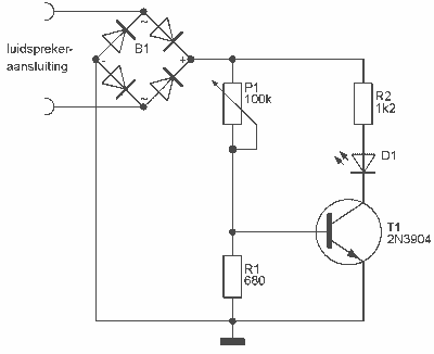
Audio Peak / Beat LED indicator
This indicator can be used, or see if your speakers can be damaged by the noise power. With P1 you can set the limit to which D1 LED lights. The pot is 100k here, you can even experiment with other...

Square-wave generator circuit
T1 and T2 in the circuit form the inherent oscillator, while T3 serves as the output stage. The network consists of a high-pass filter (C3, C4, R6, and R7) and a low-pass filter. The output from this network is fed...

100khz square wave generator
The form of a musical signal never resembles a square wave. The frequency range perceived by an average adult rarely exceeds 17 kHz. Therefore, the appropriateness of testing audio amplifiers with a 100 kHz square wave signal is often debated....

Astable Multivibrator Electronic
Function: to trigger a device or operate in free-running mode. Components: Battery, Charger, Battery Connector, Capacitor, Integrated Circuit (IC), Resistor VR1-10K, Resistor R1-1K, Resistor R2.
The described circuit functions either to trigger a connected device or to operate in a free-running...

3 square waves generator
The circuit generates three square wave outputs with a 120° phase difference between each output. The reference clock frequency is set to twice the desired output frequency. This can be achieved using a crystal oscillator followed by a series of...

Astable Multivibrator Calculations
For the time it takes to charge to 0.6V, the other capacitor has already charged significantly (a value that cannot be determined because the setup does not function until one of the two states—Q1 is on or Q2 is on—is...

how to get more power out of a astable multivibrator
Powering this circuit with a 6V alkaline battery operates effectively with 100µF capacitors. However, there is an issue when attempting to replace the LED with a DPDT relay; a 6V relay previously available does not activate. Additionally, when using a...

astable multivibrator
The astable multivibrator presented in Wikipedia and college materials is depicted on the left side of the image. In contrast, the schematic on the right side is sourced from an LTSpice example. The right schematic is incorrectly drawn, and the...

square wave generator
An electronic project to build a multivibrator as a basic first test instrument, ideal for troubleshooting radio repairs. Includes a how-to-use guide. An excellent beginner project.
The multivibrator circuit serves as a fundamental building block in electronics, providing a versatile tool...