


Atari Punk Junk Console
#LFSR
#noise generator
#DIY
#sound modulation
#electrical engineering
#test circuit
#audio oscillator
#signal modulation

Description: This circuit utilizes two fundamental oscillators that can be assembled as a DIY project, effectively modulating the primary Linear Feedback Shift Register (LFSR) circuit. It also produces interesting audio effects independently. The circuit serves as the main noise generator. The LFSR is a commonly used test circuit in electrical engineering. The power supply is designed to provide two distinct sources (battery and AC adapter), which are then regulated to deliver a stable, low-noise 5V output. A switch acts as the master on/off control for the circuit. When working with oscillators and AC adapters, it is essential to filter the power supply to prevent excess noise from interfering with sound quality, particularly during sampling or recording.
The circuit design incorporates two basic oscillators that generate audio signals, which are then used to modulate the output of the LFSR. The LFSR is a sequential circuit that produces pseudo-random binary sequences, making it suitable for applications such as noise generation and digital signal processing. The oscillators can be built using simple components such as resistors, capacitors, and transistors, allowing for easy assembly and modification.
The power supply section is critical in ensuring the stability and reliability of the circuit. It includes a voltage regulator that maintains a consistent 5V output, regardless of whether the circuit is powered by a battery or an AC adapter. This is achieved through the use of filtering capacitors that smooth out any voltage fluctuations and reduce noise. The inclusion of a master switch allows for convenient control over the entire circuit, enabling users to easily turn the system on or off as needed.
To further enhance performance, it is advisable to implement additional filtering techniques, such as using ferrite beads or inductors, to eliminate high-frequency noise that may arise from the power supply. This is particularly important in audio applications, where clarity and fidelity are paramount. Proper grounding practices should also be observed to minimize interference and maintain signal integrity throughout the circuit. Overall, this circuit design serves as a versatile platform for experimenting with sound modulation and noise generation in various electronic projects.Using two of the most basic oscillators you can DIY, this particular circuit works great to modulate our main LFSR circuit. It also sounds pretty cool on its own. The main noise generator for our circuit. The basic circuit at play here is a Linear Feedback Shift Register (LFSR), a test circuit widely used in electrical engineering.
The power supply is a standard way of offering two different power sources (battery and AC Adapter) and then regulating them to a nice, steady, low-noise 5V. The switch is the master on/off for the circuit. If you`re dealing with oscillators and AC Adapters, it behooves you to filter the power supply. You don`t want excess noise to interfere with your sounds, especially when sampling/recording!
The circuit design incorporates two basic oscillators that generate audio signals, which are then used to modulate the output of the LFSR. The LFSR is a sequential circuit that produces pseudo-random binary sequences, making it suitable for applications such as noise generation and digital signal processing. The oscillators can be built using simple components such as resistors, capacitors, and transistors, allowing for easy assembly and modification.
The power supply section is critical in ensuring the stability and reliability of the circuit. It includes a voltage regulator that maintains a consistent 5V output, regardless of whether the circuit is powered by a battery or an AC adapter. This is achieved through the use of filtering capacitors that smooth out any voltage fluctuations and reduce noise. The inclusion of a master switch allows for convenient control over the entire circuit, enabling users to easily turn the system on or off as needed.
To further enhance performance, it is advisable to implement additional filtering techniques, such as using ferrite beads or inductors, to eliminate high-frequency noise that may arise from the power supply. This is particularly important in audio applications, where clarity and fidelity are paramount. Proper grounding practices should also be observed to minimize interference and maintain signal integrity throughout the circuit. Overall, this circuit design serves as a versatile platform for experimenting with sound modulation and noise generation in various electronic projects.Using two of the most basic oscillators you can DIY, this particular circuit works great to modulate our main LFSR circuit. It also sounds pretty cool on its own. The main noise generator for our circuit. The basic circuit at play here is a Linear Feedback Shift Register (LFSR), a test circuit widely used in electrical engineering.
The power supply is a standard way of offering two different power sources (battery and AC Adapter) and then regulating them to a nice, steady, low-noise 5V. The switch is the master on/off for the circuit. If you`re dealing with oscillators and AC Adapters, it behooves you to filter the power supply. You don`t want excess noise to interfere with your sounds, especially when sampling/recording!

Sound-modulated light source
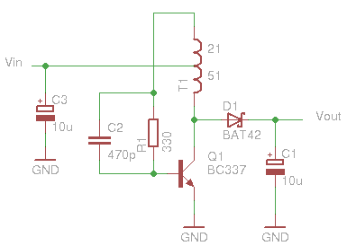
This circuit modulates a light beam using audio signals from an amplifier's output. By adjusting the 10 K potentiometer to a value slightly less than the Vbe of the transistor, the circuit operates as a peak detector. This configuration drives...
Glue stck torch
This project, developed around 2005, involves constructing a torch using a glue stick, which conveniently accommodates an AA battery within its plastic casing. To create a functional battery holder, contacts for both the positive and negative connections are necessary. The...
dyi setup and debugging guide
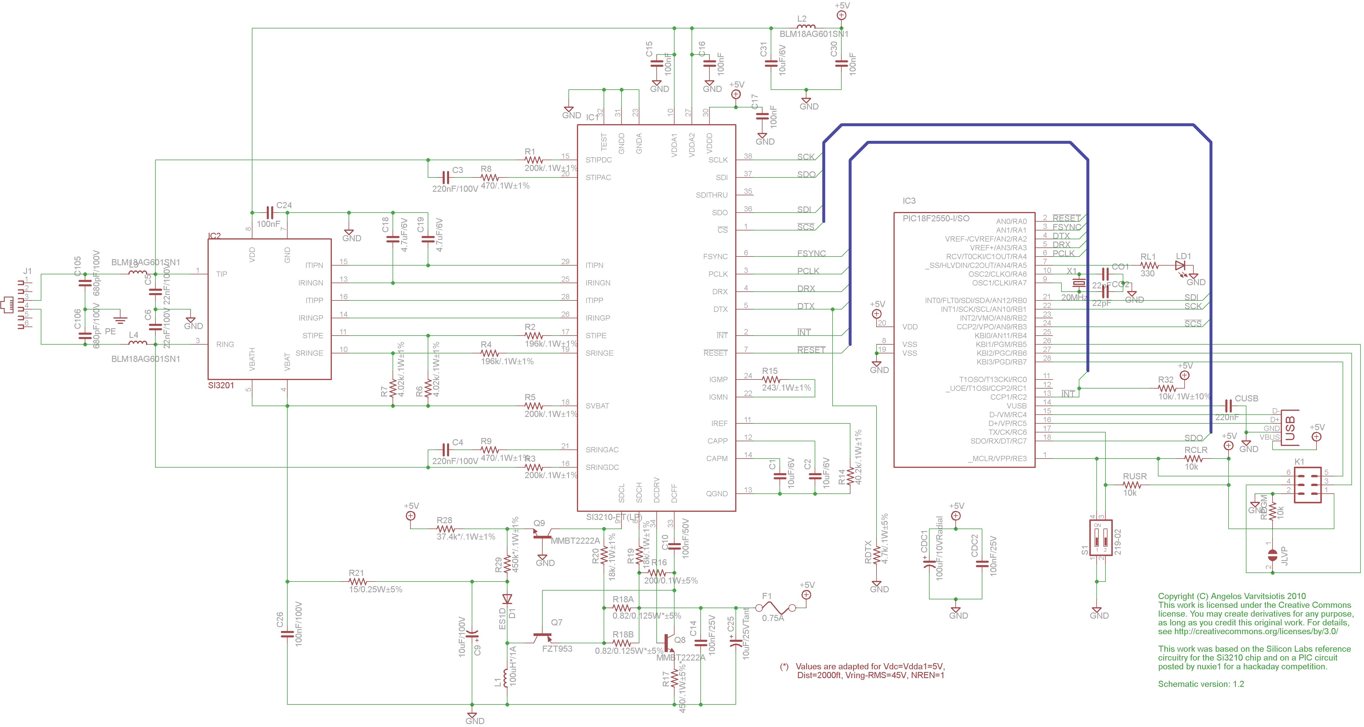
This page discusses the differences between assembled Open USB FXS dongle boards and DIY boards. While the assembled boards are fully tested and quality control approved, DIY boards may encounter various issues during assembly. Fortunately, most of these issues can...

Homemade Metal Detector Kit
A simple home project can quickly become problematic if it encounters electric cables, gas, or water pipes, or the central heating system. Using a metal detector allows one to check for metal objects within walls, ceilings, or floors beforehand. An...

how to convert a 9v battery to 3.7v
A regulator circuit is needed for this DIY project. Familiarity with electronic components, circuitry, the use of a multitester, and a soldering iron is essential. The schematic diagram provided can accept an input voltage ranging from 6 to 24 volts...

Noise Generators
This circuit is effective for testing audio circuits using broadband noise. It employs three inexpensive C-MOS integrated circuits (ICs) that produce a series of output pulses with randomly varying widths. The audio noise generator is designed to drive earphones or...

5 Minute Signal
For the past year and a half, a group based in Ann Arbor, Michigan, named GO-Tech has been formed, uniting individuals interested in creating projects using technology, such as hardware, software, metal, and wood. This initiative is referred to as...

Audio Oscillator
Two gates, U1A and U1B, of a 4049 hex inverter, are connected in a VFO circuit. Components R1, R3, and C1 set the frequency range of the VFO. With the given values, the circuit's output can range from a few...
Help with a schematic please
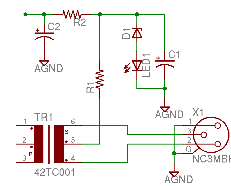
A project is underway to construct the CountryHick DI as illustrated on DIYFactory, incorporating a few minor modifications. The final design aims to be a 1U unit with four inputs.
The CountryHick DI (Direct Injection) box is a crucial tool in...