


Butler aperiodic oscillator
#Butler oscillator
#aperiodic
#50 kHz
#500 kHz
#frequency range
#component modification
#high frequency
#electronic oscillator
#RF oscillator

Description: This circuit operates effectively within the frequency range of 50 kHz to 500 kHz. Minor component modifications are required for functioning at higher frequencies. For frequencies exceeding 3000 kHz, it is advisable to choose a transistor that offers moderate gain, specifically within the range of 60 to 150, at the desired frequency, along with a gain-bandwidth product of no less than 100 MHz.
The circuit in question is designed to function optimally between 50 kHz and 500 kHz, making it suitable for applications that require precise frequency control within this bandwidth. The design allows for minor adjustments to components, enabling the circuit to adapt to higher frequency operations. When operating at frequencies above 3000 kHz, careful selection of the transistor is critical to maintain performance.
The transistor should be chosen based on its gain characteristics, specifically targeting a moderate gain between 60 and 150, which ensures that the circuit can maintain stability and efficiency at higher frequencies. Additionally, the gain-bandwidth product is a crucial parameter; a minimum of 100 MHz is recommended to ensure that the transistor can adequately amplify signals without distortion or loss of fidelity at elevated frequencies.
In practical terms, this means that the circuit may utilize a variety of transistors, including BJTs or FETs, depending on the specific application requirements. The choice of passive components, such as resistors and capacitors, may also need to be adjusted to accommodate the desired frequency response and to ensure that the overall circuit maintains its integrity across the intended frequency range. By adhering to these guidelines, the circuit can be effectively optimized for both moderate and high-frequency applications.This circuit works well in the range of 50 kHz to 500 kHz. Slight component modifications are needed for higher frequency operation For operation over 3000 kHz, select a transistor that provides moderate gain (in the 60 to 150 range) at the frequency of operation and a gain-bandwidth product of at least 100 MHz.
The circuit in question is designed to function optimally between 50 kHz and 500 kHz, making it suitable for applications that require precise frequency control within this bandwidth. The design allows for minor adjustments to components, enabling the circuit to adapt to higher frequency operations. When operating at frequencies above 3000 kHz, careful selection of the transistor is critical to maintain performance.
The transistor should be chosen based on its gain characteristics, specifically targeting a moderate gain between 60 and 150, which ensures that the circuit can maintain stability and efficiency at higher frequencies. Additionally, the gain-bandwidth product is a crucial parameter; a minimum of 100 MHz is recommended to ensure that the transistor can adequately amplify signals without distortion or loss of fidelity at elevated frequencies.
In practical terms, this means that the circuit may utilize a variety of transistors, including BJTs or FETs, depending on the specific application requirements. The choice of passive components, such as resistors and capacitors, may also need to be adjusted to accommodate the desired frequency response and to ensure that the overall circuit maintains its integrity across the intended frequency range. By adhering to these guidelines, the circuit can be effectively optimized for both moderate and high-frequency applications.This circuit works well in the range of 50 kHz to 500 kHz. Slight component modifications are needed for higher frequency operation For operation over 3000 kHz, select a transistor that provides moderate gain (in the 60 to 150 range) at the frequency of operation and a gain-bandwidth product of at least 100 MHz.

Butler Oscillator
The initial tasks involved acquiring VHF components and investigating the Butler crystal oscillator, particularly focusing on the common base variant. The VHF knowledge base is rich with established information. There are claims that the emitter follower variant of the Butler...

High Frequency Generator Circuit
This circuit design for a high-frequency waveform generator is highly beneficial for electronic experiments and designs. The circuit generates sine wave oscillations, but it can also be modified to produce triangle or square wave functions.
The high-frequency waveform generator circuit typically...

27Mhz and 49Mhz rf oscillator-transmitter
The modulator and oscillator comprise two NPN transistors. The base of the modulator transistor is powered by a bidirectional current source, with the voltage range for the high condition restricted by a saturating PNP collector connected to the pin 4...

10Mhz coaxial line driver
The circuit is ideal for high-frequency line driving systems that necessitate a wide power bandwidth at elevated output current levels. The integrated circuit used is HA2530. The bandwidth of the circuit is constrained solely by the single pole response of...
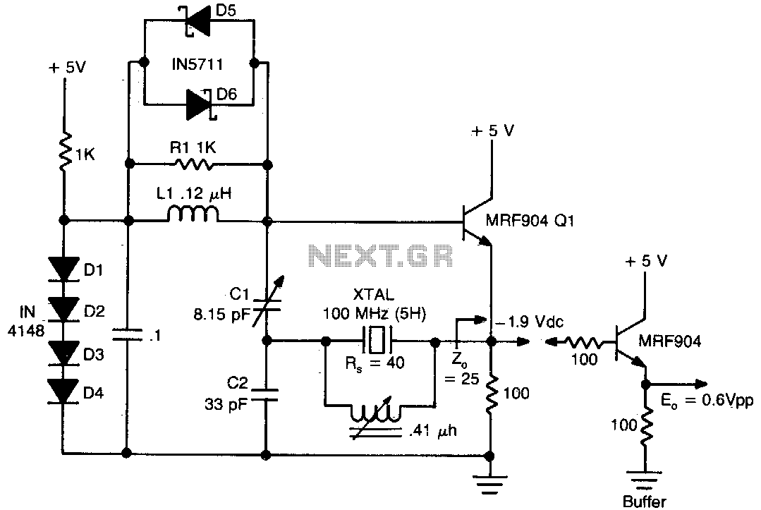
Butler emitter follower oscillator 100Mhz
This circuit exhibits good performance without an amplifier, having a gain of only one, with built-in parasitics due to the emitter follower negative feedback. Additionally, it serves to stabilize its gain.
The circuit under discussion utilizes an emitter follower configuration, which...

High Frequency Waveform GeneratorCircuit
A high-frequency waveform generator is highly beneficial for electronic experimentation and design. This circuit generates sine wave oscillations; however, it can be modified to produce triangle or square wave functions. The frequency can be controlled using current. By disconnecting the...

High Frequency Colpitts Crystal Oscillator
Op-amps have been widely used in low-frequency oscillators.
Op-amps, or operational amplifiers, are versatile components frequently utilized in the design of low-frequency oscillators. These devices are capable of generating periodic waveforms, such as sine, square, or triangular waves, which are essential...

High frequency crystal oscillator
One section of the MC10101 is configured as a 100 MHz crystal oscillator, with the crystal placed in series within the feedback loop. An LC tank circuit is utilized to tune the 100 MHz harmonic of the crystal, which can...

Rf oscillator
This RF oscillator is effective up to 30 MHz. An SK 3007 PNP transistor is recommended.
The described RF oscillator circuit operates within a frequency range of up to 30 MHz, making it suitable for various applications in radio frequency transmission...