


Cascade bandpass filters for higher Q
#bandpass filter
#switched-capacitor
#high-Q filter
#MSFS1
#Butterworth
#Bessel
#elliptic response
#seventh-order filter

Description: Switched-capacitor filters that are preset for a given bandwidth sometimes do not deliver the bandwidth or Q an application requires. By inverting the clock between two switched-capacitor bandpass filters, such as the MSFS1 from Mixed Signal Integration Corp, you can configure a high-Q filter. The MSFS1 is a selectable, seventh-order, lowpass/bandpass, switched-capacitor filter. Using the FSEL pin, you can select either a lowpass or a bandpass response. With the TYPE pin, you can select a Butterworth, a Bessel, or an elliptic response if FSEL is low.
The described circuit utilizes switched-capacitor technology to create filters with adjustable bandwidth and quality factor (Q). The MSFS1 filter is notable for its versatility, allowing designers to select different configurations to meet specific application requirements.
The operation of the MSFS1 involves the use of a clock signal to control the switching of capacitors. By inverting the clock signal between two MSFS1 units, a high-Q filter configuration can be achieved. This inversion effectively alters the timing of the charge and discharge cycles of the capacitors, leading to enhanced filter performance characteristics.
The FSEL pin is crucial for defining the filter type; setting this pin low configures the filter to operate in either lowpass or bandpass mode. This flexibility is important in applications where the desired frequency response may change. Additionally, the TYPE pin allows for the selection of different filter responses, including Butterworth for a maximally flat frequency response, Bessel for a linear phase response, or elliptic for a sharper roll-off at the expense of ripple in the passband.
In practical applications, the MSFS1 can be integrated into various electronic systems where precise filtering of signals is required, such as in audio processing, communication systems, or instrumentation. The ability to adjust the filter characteristics dynamically makes it a valuable component in modern electronic design.
Proper implementation of the MSFS1 involves careful consideration of external components, such as resistors and capacitors, to ensure stability and performance. The design should also account for power supply decoupling and layout considerations to minimize noise and interference, which are critical for maintaining the integrity of the filtered signals.Switched-capacitor filters that are preset for a given bandwidth sometimes do not deliver the bandwidth or Q an application requires. By inverting the clock between two switched-capacitor bandpass filters, such as the MSFS1 from Mixed Signal Integration Corp, you can configure a high-Q filter (Figure 1).
The MSFS1 is a selectable, seventh-order, lowpass/bandpass, switched-capacitor filter. Using the FSEL pin, you can select either a lowpass or a bandpass response. With the TYPE pin, you can select a Butterworth, a Bessel, or an elliptic response if FSEL is low.
The described circuit utilizes switched-capacitor technology to create filters with adjustable bandwidth and quality factor (Q). The MSFS1 filter is notable for its versatility, allowing designers to select different configurations to meet specific application requirements.
The operation of the MSFS1 involves the use of a clock signal to control the switching of capacitors. By inverting the clock signal between two MSFS1 units, a high-Q filter configuration can be achieved. This inversion effectively alters the timing of the charge and discharge cycles of the capacitors, leading to enhanced filter performance characteristics.
The FSEL pin is crucial for defining the filter type; setting this pin low configures the filter to operate in either lowpass or bandpass mode. This flexibility is important in applications where the desired frequency response may change. Additionally, the TYPE pin allows for the selection of different filter responses, including Butterworth for a maximally flat frequency response, Bessel for a linear phase response, or elliptic for a sharper roll-off at the expense of ripple in the passband.
In practical applications, the MSFS1 can be integrated into various electronic systems where precise filtering of signals is required, such as in audio processing, communication systems, or instrumentation. The ability to adjust the filter characteristics dynamically makes it a valuable component in modern electronic design.
Proper implementation of the MSFS1 involves careful consideration of external components, such as resistors and capacitors, to ensure stability and performance. The design should also account for power supply decoupling and layout considerations to minimize noise and interference, which are critical for maintaining the integrity of the filtered signals.Switched-capacitor filters that are preset for a given bandwidth sometimes do not deliver the bandwidth or Q an application requires. By inverting the clock between two switched-capacitor bandpass filters, such as the MSFS1 from Mixed Signal Integration Corp, you can configure a high-Q filter (Figure 1).
The MSFS1 is a selectable, seventh-order, lowpass/bandpass, switched-capacitor filter. Using the FSEL pin, you can select either a lowpass or a bandpass response. With the TYPE pin, you can select a Butterworth, a Bessel, or an elliptic response if FSEL is low.

Active bandpass filter principle
The performance of a second-order band-pass filter is primarily influenced by the quality factor (Q) and the center frequency (Si). To adjust the Q value, R3 should be modified first, followed by adjustments to C0. However, these adjustments will also...

Single Op-Amp Bandpass Filter circuit
A bandpass filter allows a specific range of frequencies to pass while rejecting frequencies that fall outside the upper and lower limits of the passband. The frequencies that are permitted to pass are referred to as the passband, which extends...
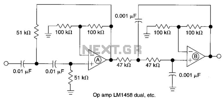
Active Second-Order Bandpass Filter Circuit
This filter circuit, which utilizes the LM1458 or a similar operational amplifier, has a frequency response ranging from 300 Hz to 3.4 kHz, exhibiting a roll-off of 12 dB per octave outside the passband. Section A serves as the high-pass...
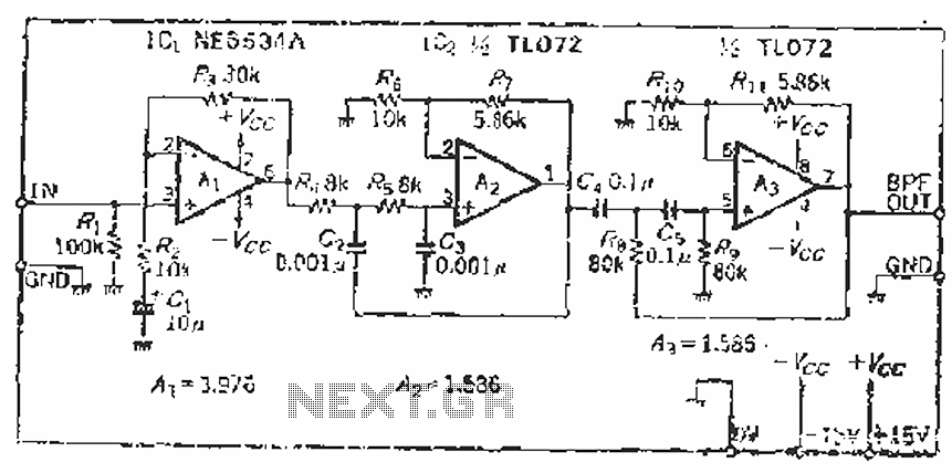
Measuring SN audio bandpass filter circuit
The filter incorporates a zoom function, with a front satin amplifier magnification calculated as d = 10/2.515 = 3.97, which results in a total beam compared to a 10 times magnification. The low-pass filter parameters are specified as a cutoff...

RAZOR SHARP CW FILTER
The circuit comprises four stages of active bandpass filtering, utilizing two A747 integrated-circuit dual operational amplifiers. It incorporates a simple threshold detector, consisting of diodes D1 and D2, positioned between stages 2 and 3 to minimize low-level background noise. Each...

Musical chime generator
The circuit is a multiple feedback bandpass filter. A brief click (pulse) causes it to resonate at its natural frequency. The oscillations diminish exponentially, closely resembling various naturally occurring percussive or plucked sounds. The higher the quality factor (Q), the...

Bandpass and notch filter
The Quad op-amp MC4301 is employed to configure a filter that eliminates a specific frequency, outputting the notched frequency at the BP terminal. This is particularly useful in communication or measurement setups. By selecting appropriate components, filters capable of targeting...

Variable Bandpass Audio Filter Circuit
This circuit is a variable audio bandpass filter that features a low cutoff adjustable from approximately 25 Hz to 700 Hz and a high cutoff adjustable from 2.5 kHz to over 20 kHz. The roll-off is set at 12 dB/octave...

Voice bandpass circuit diagram
The circuit provides an 8-ohm output for connecting communication receivers and low-impedance speakers or headphones, featuring harmful interference suppression for continuous random voice transmission. The passband ranges from 55 to 2530 Hz with a 3 dB bandwidth. Inductors L1 and...