


CW Practice oscillator
#CW Morse code
#NE 555
#astable multivibrator
#Ham Radio
#practice oscillator
#frequency
#R1
#R2
#C1
#9V PP3
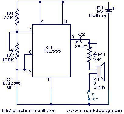
Description: A circuit diagram for generating continuous wave (CW) Morse code is presented here. This circuit is particularly beneficial for individuals interested in practicing Ham Radio. It consists of an astable multivibrator utilizing the NE555 timer. The oscillation frequency of the circuit is determined by the components R1, R2, and C1. The circuit can be powered by a 9V PP3 battery.
The proposed circuit employs the NE555 timer in an astable configuration to generate a square wave output, which can be used to produce Morse code signals. In this setup, the timer continuously switches between its high and low states, creating a tone that can be modulated to represent Morse code. The frequency of oscillation, which dictates the speed of the Morse code output, is influenced by the resistors R1 and R2, as well as the capacitor C1.
The relationship governing the frequency (f) of the output waveform can be expressed by the formula:
f = 1.44 / ((R1 + 2 * R2) * C1)
Where:
- R1 is the resistance connected from the discharge pin to VCC,
- R2 is the resistance connected from the discharge pin to the threshold pin, and
- C1 is the timing capacitor connected to the threshold pin and ground.
Adjusting R1, R2, or C1 will allow users to modify the frequency of the output signal, thereby enabling the generation of different Morse code speeds.
The circuit requires a 9V PP3 battery for power, which is connected to the VCC pin of the NE555 timer. The output pin of the NE555 timer can be connected to a speaker or a piezo buzzer to produce audible tones. Additionally, a simple switch can be included to enable or disable the output signal, allowing for convenient operation during practice sessions.
Overall, this circuit serves as an effective tool for amateur radio enthusiasts to practice and improve their Morse code skills, providing a hands-on approach to learning and enhancing communication abilities in the amateur radio community.A circuit diagram that can be used for the generation of CW Morse code is shown here. This circuit can be very useful those who would like practice Ham Radio. The circuit is nothing but an astable multivibrator based on NE 555. The frequency of oscillations of the circuit depends on the components R1, R2 & C1. The circuit can be powered from a 9V PP3 b attery.
The proposed circuit employs the NE555 timer in an astable configuration to generate a square wave output, which can be used to produce Morse code signals. In this setup, the timer continuously switches between its high and low states, creating a tone that can be modulated to represent Morse code. The frequency of oscillation, which dictates the speed of the Morse code output, is influenced by the resistors R1 and R2, as well as the capacitor C1.
The relationship governing the frequency (f) of the output waveform can be expressed by the formula:
f = 1.44 / ((R1 + 2 * R2) * C1)
Where:
- R1 is the resistance connected from the discharge pin to VCC,
- R2 is the resistance connected from the discharge pin to the threshold pin, and
- C1 is the timing capacitor connected to the threshold pin and ground.
Adjusting R1, R2, or C1 will allow users to modify the frequency of the output signal, thereby enabling the generation of different Morse code speeds.
The circuit requires a 9V PP3 battery for power, which is connected to the VCC pin of the NE555 timer. The output pin of the NE555 timer can be connected to a speaker or a piezo buzzer to produce audible tones. Additionally, a simple switch can be included to enable or disable the output signal, allowing for convenient operation during practice sessions.
Overall, this circuit serves as an effective tool for amateur radio enthusiasts to practice and improve their Morse code skills, providing a hands-on approach to learning and enhancing communication abilities in the amateur radio community.A circuit diagram that can be used for the generation of CW Morse code is shown here. This circuit can be very useful those who would like practice Ham Radio. The circuit is nothing but an astable multivibrator based on NE 555. The frequency of oscillations of the circuit depends on the components R1, R2 & C1. The circuit can be powered from a 9V PP3 b attery.

Hee-haw
The circuit utilizes two gates from a 7400 integrated circuit, cross-connected to create an astable multivibrator that is driven by the one pulse per second output from a digital clock integrated circuit. Additionally, the circuit incorporates a low-frequency astable modulator...

KC2ZPLs Web Design and Electronic Home
KC2ZPL Web Design, electronics, HAM radio, CW, homebrew construction, general electronics, high voltage, experimenter's web page.
The KC2ZPL web page serves as a comprehensive resource for individuals interested in various aspects of electronics and amateur radio (HAM radio). It covers a...

Mosquito repelant circuit
The Astable Multivibrator, which is generally used as a signal generator, is once again used here to generate the desired frequencies. It is an excellent example of the fact, how versatile simple basic electronic circuit can be. It seems quite...

Starting Network for Astable Multivibrator
An astable multivibrator is a flip-flop that produces two unstable states (high and low), functioning as an oscillator.
An astable multivibrator is a fundamental electronic circuit that continuously switches between its two states without requiring any external triggering signals. This...

Toss-a-coin binary box
The circuit employs an astable multivibrator to alternate between heads and tails conditions, while a flip-flop is utilized to retain the state determined by the multivibrator. As a result, the circuit is designed so that the flip-flop's state changes once...

Pal decoder
After several years, the NMS8280 was utilized again for HAM radio purposes. When transmitting a signal, radio amateurs must always identify themselves by providing their callsign, which also applies to video signal transmission. A program was created using the WBASS...

Circuit operation explanation of astable multivibrator
The circuit does not fail under slight variations, even if the input/output electric current characteristics are exceeded. Failure occurs only during a short circuit or extreme conditions at the output. The operation of the circuit is explained as follows: the...

Simple Ham Radio Circuit Audio Filter With 741 IC
This circuit will filter out interference signals and ensure that the signal received from the Morse code station stands out.
The described circuit functions as a signal processing system specifically designed to enhance the clarity of Morse code transmissions by minimizing...

Astable Multivibrator Calculations
For the time it takes to charge to 0.6V, the other capacitor has already charged significantly (a value that cannot be determined because the setup does not function until one of the two states—Q1 is on or Q2 is on—is...