


Drawing circles on a scope
#quadrature oscillator
#sine wave
#cosine wave
#signal generator
#waveform
#analog circuit
#electronics
#function generator
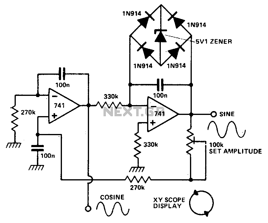
Description: The circuit is a quadrature sine and cosine oscillator. To generate circular displays, connect the two outputs to the X and Y inputs.
The quadrature sine and cosine oscillator circuit is designed to produce two output waveforms that are 90 degrees out of phase, which are essential for applications such as generating circular displays in oscilloscopes or other graphical representations. The oscillator typically employs an arrangement of operational amplifiers or specialized waveform generator ICs configured to produce sine and cosine signals.
In a standard implementation, the circuit may utilize a phase-locked loop (PLL) to maintain the precise phase relationship between the two outputs. The sine output can be derived from a Wien bridge oscillator or a similar configuration, while the cosine output is obtained through a phase-shifting network that introduces a 90-degree phase delay.
The outputs of the oscillator are connected to the X and Y inputs of a display system, such as an oscilloscope or a vector graphics display. By feeding the sine wave to one axis (X) and the cosine wave to the other axis (Y), a circular trace is produced on the display, effectively visualizing the parametric equations of a circle.
In practical applications, the oscillator's frequency can be adjusted to control the speed of the circular display, and additional components may be incorporated to stabilize the output amplitudes and minimize distortion. Proper power supply decoupling and filtering techniques are also essential to ensure the reliable operation of the oscillator circuit.The circuit is that of a quadrature sine and cosine oscillator To generate circular displays, connect the two outputs to the X and Y inputs.
The quadrature sine and cosine oscillator circuit is designed to produce two output waveforms that are 90 degrees out of phase, which are essential for applications such as generating circular displays in oscilloscopes or other graphical representations. The oscillator typically employs an arrangement of operational amplifiers or specialized waveform generator ICs configured to produce sine and cosine signals.
In a standard implementation, the circuit may utilize a phase-locked loop (PLL) to maintain the precise phase relationship between the two outputs. The sine output can be derived from a Wien bridge oscillator or a similar configuration, while the cosine output is obtained through a phase-shifting network that introduces a 90-degree phase delay.
The outputs of the oscillator are connected to the X and Y inputs of a display system, such as an oscilloscope or a vector graphics display. By feeding the sine wave to one axis (X) and the cosine wave to the other axis (Y), a circular trace is produced on the display, effectively visualizing the parametric equations of a circle.
In practical applications, the oscillator's frequency can be adjusted to control the speed of the circular display, and additional components may be incorporated to stabilize the output amplitudes and minimize distortion. Proper power supply decoupling and filtering techniques are also essential to ensure the reliable operation of the oscillator circuit.The circuit is that of a quadrature sine and cosine oscillator To generate circular displays, connect the two outputs to the X and Y inputs.
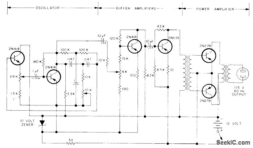
100W SINE AT 60Hz
The circuit primarily comprises a 60-Hz sine-wave oscillator featuring a 10K frequency-control potentiometer, two buffering stages, and a push-pull power amplifier. This design effectively addresses the noise issues associated with square-wave inverters, particularly when powering a 115-V radio receiver or...

Self Powered Sine Wave to Square Converter
This circuit utilizes a single active component, the 4069 IC, to convert sine waves into square waves without requiring an external power source. It is designed for testing audio instruments.
The circuit leverages the characteristics of the 4069 IC, which is...

DIY Homemade Signal Generator with Pulse Width Modulation
Construct a signal generator using readily available components. It should produce a square wave with variable frequency and adjustable pulse width. This device can be utilized for various applications, including DC motor speed regulation, dimming of lamps or LEDs, transformer...

SINE WAVE TO SQUARE WAVE CONVERTER
This circuit converts a sine wave into a square wave. It consists of a single 2-input NAND Schmitt trigger configured as an inverter, with a trigger level adjustment at its input. As the input voltage exceeds the gate's trigger point,...

A Simple Sine Wave Oscillator
After constructing the device, adjust the frequency to the desired level using the "Frequency Control." Then, utilize an oscilloscope to fine-tune the waveform for optimal performance with the "Clip Control." The sharp rise and fall times of square waves cause...

DIY Audio Function Generator Part 1
A simple low-end audio function generator is being designed to utilize a sine wave output for testing ADC resolution and as a baseband signal for RF projects, with an emphasis on achieving very low total harmonic distortion (THD). The approach...

Analog circuit enforces slow servo response
The all-analog circuit presented controls the rate at which a miniature turbojet engine can be throttled. Increasing or decreasing the throttle too quickly on a miniature turbojet engine, or any jet engine, can lead to quick failure in flight, causing...

Single-control-function-generator
This function generator features an adjustment range exceeding 1,000,000 to 1 and utilizes a CA3160 BiMOS operational amplifier as a voltage follower. It incorporates a CA3080 operational transconductance amplifier (OTA) as a high-speed comparator, alongside another CA3080 configured as a...

Simple Function Generator Circuit
This is a design circuit for a simple function generator. Built around a single 8038 waveform generator IC, this circuit produces sine, square, or triangle waves from 20Hz to 200kHz in four switched ranges. There are both high and low-level...