


electronic marx circuit and gas
#Marx generator
#high voltage
#pulse generation
#capacitors
#spark gap
#energy storage
#circuit configuration
#electrical discharge
#voltage multiplier
#pulse circuits

Description: Writing about multiple circuits in Marx, an entire new set has been discovered, referred to as "the" Marx Generator. There are diagrams available, along with a useful quote: "The main advantage of the Marx circuit configuration over a more direct approach to charging is that it overcomes..."
The Marx generator is a type of electrical circuit used to generate high-voltage pulses. It consists of a series of capacitors and spark gaps arranged in a specific configuration to achieve rapid charging and discharging. The basic principle involves charging multiple capacitors in parallel and then discharging them in series, which results in a high-voltage output.
In a typical Marx generator setup, several capacitors are connected to a common voltage source. Each capacitor charges up to the source voltage. Once the capacitors are fully charged, the spark gaps are triggered, creating a conductive path between them. This allows the stored energy in the capacitors to discharge through the spark gaps in series, effectively adding the voltages of each capacitor together. The result is a much higher voltage pulse than what would be possible with a single capacitor alone.
The configuration of the Marx generator allows for precise control over the timing of the discharge, which is crucial for applications such as high-voltage testing, pulsed power applications, and electromagnetic pulse (EMP) generation. Additionally, the ability to scale the generator by adding more capacitors and spark gaps provides flexibility in designing circuits for specific high-voltage requirements.
The advantages of the Marx generator include its simplicity, efficiency in generating high-voltage pulses, and the ability to produce short-duration, high-energy outputs. It is commonly used in research laboratories, industrial applications, and as a component in various high-voltage experiments. Understanding the operational principles and configuration of the Marx generator is essential for engineers and researchers working in fields that require high-voltage technology.Writing about multiple circuits in Marx, I have just discovered (shame for not knowing this) an entire new set - indeed, billed as `the` Marx Generator. There are, of course, also diagrams, and a useful quote: `The main advantage of the Marx circuit configuration over a more direct approach to charging is that it overcomes..
The Marx generator is a type of electrical circuit used to generate high-voltage pulses. It consists of a series of capacitors and spark gaps arranged in a specific configuration to achieve rapid charging and discharging. The basic principle involves charging multiple capacitors in parallel and then discharging them in series, which results in a high-voltage output.
In a typical Marx generator setup, several capacitors are connected to a common voltage source. Each capacitor charges up to the source voltage. Once the capacitors are fully charged, the spark gaps are triggered, creating a conductive path between them. This allows the stored energy in the capacitors to discharge through the spark gaps in series, effectively adding the voltages of each capacitor together. The result is a much higher voltage pulse than what would be possible with a single capacitor alone.
The configuration of the Marx generator allows for precise control over the timing of the discharge, which is crucial for applications such as high-voltage testing, pulsed power applications, and electromagnetic pulse (EMP) generation. Additionally, the ability to scale the generator by adding more capacitors and spark gaps provides flexibility in designing circuits for specific high-voltage requirements.
The advantages of the Marx generator include its simplicity, efficiency in generating high-voltage pulses, and the ability to produce short-duration, high-energy outputs. It is commonly used in research laboratories, industrial applications, and as a component in various high-voltage experiments. Understanding the operational principles and configuration of the Marx generator is essential for engineers and researchers working in fields that require high-voltage technology.Writing about multiple circuits in Marx, I have just discovered (shame for not knowing this) an entire new set - indeed, billed as `the` Marx Generator. There are, of course, also diagrams, and a useful quote: `The main advantage of the Marx circuit configuration over a more direct approach to charging is that it overcomes..
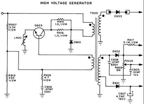
High Voltafe Generator
This is a series regulator with Q900 being the control element, Q901 a driver, and Q902 an error amp. ZD900 forms the emitter reference voltage source. Since the generated high voltage and other voltages are linked by means of the...

Tesla Coils
The history of Nikola Tesla and Tesla Coils, how a Tesla Coil works, and an example of a homemade Tesla Coil. The homemade DIY Tesla Coil is battery-operated and has a gas plasma discharge terminal. Arcs can be made to...

High Voltage Inverter
This is a simple high-voltage inverter circuit. It uses an NPN transistor type 2N3055. This circuit is designed to invert low voltage to high voltage.
The high-voltage inverter circuit utilizing the 2N3055 NPN transistor serves as an effective means to convert...

High voltage generator circuit
This circuit is highly dangerous due to its output voltage, which is in kilovolts and poses a significant risk of serious injury or death. It should only be attempted by individuals with extensive experience in handling high voltages. No responsibility...

HV REGULATOR WITH FOLDBACK CURRENT LIMITING
A TMOS MTM7N45 (Q2) functions as a series pass element in a linear high voltage supply that accepts +275 V unregulated input and produces a regulated output of 250 V, incorporating foldback current limiting. A 15 V zener diode, D1,...

Solid State Tesla Coil/High Voltage Generator Circuit
This circuit is designed to demonstrate high frequency and high voltage, capable of producing up to approximately 30 kV, depending on the transformer utilized. It is an economical and straightforward project, primarily using a standard TV flyback transformer. The circuit...

2000V Low-Current Power Supply
This circuit consists of components Q1, Q2, R1, and C1, which together create a multivibrator. The oscillation produced results in a square wave with a voltage peak-to-peak (Vpp) ranging from 20 to 30 volts. This output is then amplified by...
Gray Tube Replication 74
Geotron, I have damaged a few components myself. What type of bridge do you have connected to it? When I used a 1kV bridge made from four 6A100 diodes, I encountered issues.
In this context, the discussion revolves around the use...

hv generator circuit
This circuit is designed to demonstrate high frequency and high voltage, capable of producing approximately 30kV, depending on the transformer utilized. It is cost-effective and straightforward to construct, primarily using a standard TV flyback transformer. This circuit can power lasers,...