


Function Oscillator using 8083
#function oscillator
#8038 IC
#waveform generator
#sine wave
#square wave
#triangle wave
#frequency range
#hobbyist
#bench tool

Description: Built around a single 8038 waveform generator IC, this circuit produces sine, square or triangle waves from 20Hz to 200kHz in four switched ranges. There are both high and low level outputs which may be adjusted with the level control. This project makes a useful addition to any hobbyists workbench as well. The waveform generation is produced by IC1. This versatile IC even has a sweep input, but is not used in this circuit. The IC contains an internal squarewave oscillator, the frequency of which is controlled by timing capacitors C1 - C4 and the 10k potentiometer. The tolerance of the capacitors should be 10% or better for stability. The squarewave is differentiated to produce a triangular wave, which in turn is shaped to produce a sine wave. All this is done internally, with a minimum of external components. The purity of the sine wave is adjusted by the two 100k preset resistors. The wave shape switch is a single pole 3 way rotary switch, the wiper arm selects the wave shape and is connected to a 10k potentiometer which controls the amplitude of all waveforms. IC2 is an LF351 op-amp wired as a standard direct coupled non-inverting buffer, providing isolation between the waveform generator, and also increasing output current. The 2.2k and 47 ohm resistors form the output attenuator. At the high output, the maximum amplitude is about 8V pk-pk with the square wave. The maximum for the triangle and sine waves is around 6V and 4V respectively. The low amplitude controls is useful for testing amplifiers, as amplitudes of 20mV and 50mV are easily achievable. The two 100k preset resistors adjust the purity of the sine wave. If adjusted correctly, then the distortion amounts to less than 1%.
This circuit utilizes the 8038 waveform generator integrated circuit (IC1) as the core component for generating various waveforms, including sine, square, and triangle waves, across a frequency range of 20Hz to 200kHz. The circuit design incorporates a four-range switch that allows the user to select the desired frequency range effectively. The output levels can be adjusted using a level control, providing flexibility for different applications.
The frequency generation relies on the internal squarewave oscillator of the 8038, which is modulated by external timing capacitors (C1 to C4) and a 10k potentiometer. It is crucial that the capacitors used in this application have a tolerance of 10% or better to ensure frequency stability. The square wave output from IC1 is then differentiated to create a triangular wave, which is subsequently shaped into a sine wave. The internal design minimizes the need for external components, enhancing the circuit's compactness and reliability.
For sine wave purity, two 100k preset resistors are employed to fine-tune the waveform, ensuring that the distortion remains below 1% when optimally adjusted. The circuit includes a single pole three-way rotary switch to select the waveform type, which is connected to a 10k potentiometer responsible for controlling the amplitude across all generated waveforms.
The output stage features an LF351 operational amplifier (IC2) configured as a direct-coupled non-inverting buffer. This configuration serves to isolate the waveform generator from the load, while also increasing the output current capability. The output attenuator is constructed using a 2.2k resistor in series with a 47-ohm resistor, allowing for precise control of output levels.
At the high output setting, the circuit can deliver a peak-to-peak voltage of approximately 8V for the square wave, while the maximum outputs for the triangle and sine waves are around 6V and 4V, respectively. The low amplitude settings are particularly beneficial for testing purposes, enabling output levels of 20mV and 50mV to be easily achieved, which is essential for interfacing with sensitive amplifiers and other electronic devices.Built around a single 8038 waveform generator IC, this circuit produces sine, square or triangle waves from 20Hz to 200kHz in four switched ranges. There are both high and low level outputs which may be adjusted with the level control. This project makes a useful addition to any hobbyists workbench as well. The waveform generation is produced by IC1. This versatile IC even has a sweep input, but is not used in this circuit. The IC contains an internal squarewave oscillator, the frequency of which is controlled by timing capacitors C1 - C4 and the 10k potentiometer.
The tolerance of the capacitors should be 10% or better for stability. The squarewave is differentiated to produce a triangular wave, which in turn is shaped to produce a sine wave. All this is done internally, with a minimum of external components. The purity of the sine wave is adjusted by the two 100k preset resistors. The wave shape switch is a single pole 3 way rotary switch, the wiper arm selects the wave shape and is connected to a 10k potentiometer which controls the amplitude of all waveforms.
IC2 is an LF351 op-amp wired as a standard direct coupled non-inverting buffer, providing isolation between the waveform generator, and also increasing output current. The 2.2k and 47 ohm resistors form the output attenuator. At the high output, the maximum amplitude is about 8V pk-pk with the square wave. The maximum for the triangle and sine waves is around 6V and 4V respectively. The low amplitude controls is useful for testing amplifiers, as amplitudes of 20mV and 50mV are easily achievable.
The two 100k preset resistors adjust the purity of the sine wave. If adjusted correctly, then the distortion amounts to less than 1%.
This circuit utilizes the 8038 waveform generator integrated circuit (IC1) as the core component for generating various waveforms, including sine, square, and triangle waves, across a frequency range of 20Hz to 200kHz. The circuit design incorporates a four-range switch that allows the user to select the desired frequency range effectively. The output levels can be adjusted using a level control, providing flexibility for different applications.
The frequency generation relies on the internal squarewave oscillator of the 8038, which is modulated by external timing capacitors (C1 to C4) and a 10k potentiometer. It is crucial that the capacitors used in this application have a tolerance of 10% or better to ensure frequency stability. The square wave output from IC1 is then differentiated to create a triangular wave, which is subsequently shaped into a sine wave. The internal design minimizes the need for external components, enhancing the circuit's compactness and reliability.
For sine wave purity, two 100k preset resistors are employed to fine-tune the waveform, ensuring that the distortion remains below 1% when optimally adjusted. The circuit includes a single pole three-way rotary switch to select the waveform type, which is connected to a 10k potentiometer responsible for controlling the amplitude across all generated waveforms.
The output stage features an LF351 operational amplifier (IC2) configured as a direct-coupled non-inverting buffer. This configuration serves to isolate the waveform generator from the load, while also increasing the output current capability. The output attenuator is constructed using a 2.2k resistor in series with a 47-ohm resistor, allowing for precise control of output levels.
At the high output setting, the circuit can deliver a peak-to-peak voltage of approximately 8V for the square wave, while the maximum outputs for the triangle and sine waves are around 6V and 4V, respectively. The low amplitude settings are particularly beneficial for testing purposes, enabling output levels of 20mV and 50mV to be easily achieved, which is essential for interfacing with sensitive amplifiers and other electronic devices.Built around a single 8038 waveform generator IC, this circuit produces sine, square or triangle waves from 20Hz to 200kHz in four switched ranges. There are both high and low level outputs which may be adjusted with the level control. This project makes a useful addition to any hobbyists workbench as well. The waveform generation is produced by IC1. This versatile IC even has a sweep input, but is not used in this circuit. The IC contains an internal squarewave oscillator, the frequency of which is controlled by timing capacitors C1 - C4 and the 10k potentiometer.
The tolerance of the capacitors should be 10% or better for stability. The squarewave is differentiated to produce a triangular wave, which in turn is shaped to produce a sine wave. All this is done internally, with a minimum of external components. The purity of the sine wave is adjusted by the two 100k preset resistors. The wave shape switch is a single pole 3 way rotary switch, the wiper arm selects the wave shape and is connected to a 10k potentiometer which controls the amplitude of all waveforms.
IC2 is an LF351 op-amp wired as a standard direct coupled non-inverting buffer, providing isolation between the waveform generator, and also increasing output current. The 2.2k and 47 ohm resistors form the output attenuator. At the high output, the maximum amplitude is about 8V pk-pk with the square wave. The maximum for the triangle and sine waves is around 6V and 4V respectively. The low amplitude controls is useful for testing amplifiers, as amplitudes of 20mV and 50mV are easily achievable.
The two 100k preset resistors adjust the purity of the sine wave. If adjusted correctly, then the distortion amounts to less than 1%.
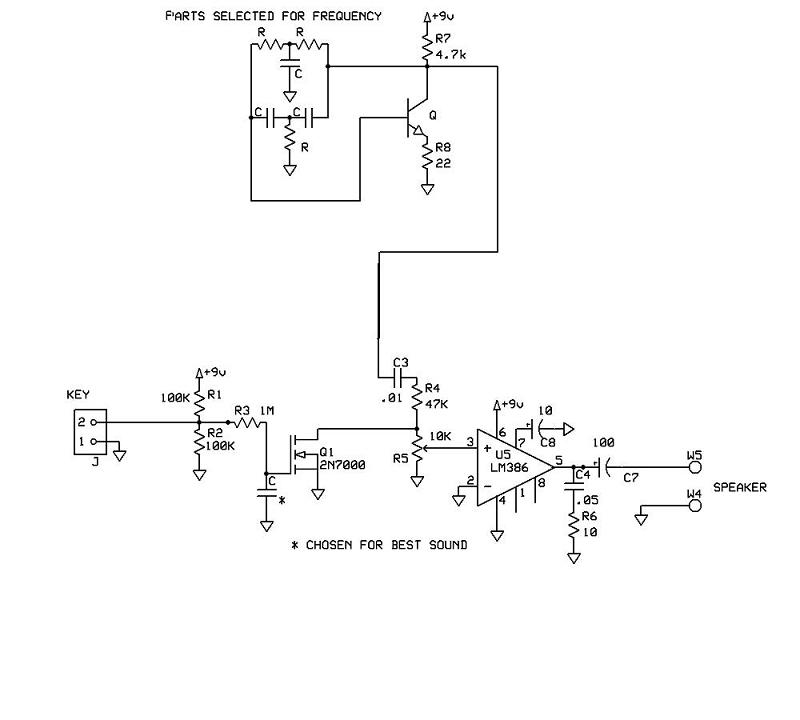
Sine wave code practice oscillator
A schematic for a code practice oscillator is needed, which can be connected to a keyer. The desired setup involves using a Picokeyer, allowing the oscillator to be plugged into the key jack of the Picokeyer. The output should drive...

square wave oscillator circuit
A simple square wave oscillator can be created using two gates from a CMOS 4011 NAND chip. Alternatively, a CMOS 4001 chip or a TTL equivalent can also be utilized. In this circuit, the mark-space ratio can be independently controlled...

Wien Bridge Sine Wave Oscillator
Achieving the appropriate amplifier loop gain is a significant challenge in generating a low distortion, constant amplitude sine wave. Nevertheless, this issue can be addressed with...
Amplifier loop gain is a critical parameter in the design of audio and signal processing...

LC square wave generator
A square-wave generator utilizing an LC circuit can achieve improved frequency stability, as illustrated in the accompanying chart. This three-terminal capacitor oscillator is capable of generating a square wave, with an operational amplifier serving as the active component.
The square-wave generator...

tuned sine wave oscillator circuit
This design circuit functions as a sine wave oscillator, providing both sine and square wave outputs across a frequency range from below 20 Hz to above 20 KHz. The oscillation frequency can be easily adjusted by varying a single resistor....

LOW frequency square wave oscillator circuit
A simple circuit that can generate an inverted square wave similar to the one used by the inventor on his function generator.
To construct a circuit that produces an inverted square wave, a basic approach involves using a 555 timer IC...

Square Wave Oscillator using Comparator/Op-Amp
The circuit depicted in this schematic diagram is a square-wave oscillator circuit. The primary component of this oscillator circuit is the LP165/365 comparator.
The square-wave oscillator circuit utilizes the LP165/365 comparator to generate a continuous square wave output. The operation...

Square-wave generator circuit
T1 and T2 in the circuit form the inherent oscillator, while T3 serves as the output stage. The network consists of a high-pass filter (C3, C4, R6, and R7) and a low-pass filter. The output from this network is fed...
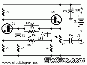
Sine Wave Generator (1KHz Frequency)
This is a kHz sine wave generator circuit built based on the configuration of an inverted Wien bridge (see C1-R3 C2-R4). R5 and R7 are used for output amplitude setting. Set R5 to read 1V RMS on an audio millivoltmeter...