


Isolated 1-Hz Clock
#1-Hz clock
#CMOS
#4017 counter
#precision timing
#quartz crystal
#frequency divider
#physics project
#clock signal
#high frequency
#CMOS logic

Description: One of the author's physics projects required an accurate 1-Hz clock signal. Unfortunately, precision 10-MHz quartz crystals are expensive, and most common 40xx CMOS logic chips cannot operate at such high frequencies. However, a typical CMOS counter like the 4017 has a high input resistance, allowing its clock input to exhibit radio frequency properties. This effect is utilized to convert the stray magnetic field from a mains transformer into a clock signal. A short piece of wire (approximately 5 cm) is connected to the clock input of a CD4017 decade counter for division by 10. The resulting 5-Hz signal is then further divided by a second 4017 (IC2) to produce a 1-Hz output. An LED (D1) flashes to indicate the presence of a sufficiently strong magnetic field. The pickup wire should be positioned close to the mains transformer, ensuring electrical safety is not compromised. The maximum distance at which a reliable clock signal is generated should always be used. For achieving a 1-Hz output from 60-Hz power systems, output 6 of IC2 (pin 5) should be utilized.
The circuit operates by harnessing electromagnetic interference from nearby mains transformers to generate a clock signal. The CD4017 decade counter is adept at functioning with minimal input signals due to its high input resistance, making it suitable for this application. The initial signal is induced in the wire, which acts as an antenna, capturing the magnetic field fluctuations. This induced signal is fed into the clock input of the first CD4017, which divides the frequency by 10, yielding a 5-Hz output.
Subsequently, this 5-Hz signal is routed to a second CD4017 (IC2), which further divides the frequency by 5, resulting in a final output of 1 Hz. The use of two counters allows for effective frequency division without the need for expensive high-frequency components. Additionally, the LED indicator (D1) provides a visual cue for the strength of the magnetic field, ensuring that the circuit operates within a suitable range for reliable clock signal generation.
For optimal performance, it is crucial to position the pickup wire as close as safely possible to the mains transformer while avoiding any potential electrical hazards. The design illustrates a creative solution to generating a low-frequency clock signal using readily available components and ambient electromagnetic fields, showcasing the versatility of CMOS logic in unconventional applications. This circuit can be integrated into various projects requiring low-frequency timing signals, especially in educational settings where budget constraints may limit access to precision timing components.One of the author`s physics projects required an accurate 1-Hz (seconds) clock signal. Unfortunately, precision 10-MHz quartz crystals are expensive, while another problem was found in the inability of most common or garden 40xx CMOS logic chips to work at such a high frequency. However, a typical CMOS counter like the 4017 has such a high input r esistance that its clock input has radio` properties. The effect is exploited here to convert the stray magnetic field picked up from a mains transformer into a clock signal. Here, the signal is induced in a short piece of wire (approx. 5 cm) connected to the clock input of a CD4017 decade counter for division by 10. The resulting 5-Hz signal is then divided by 5 by a second 4017 (IC2) to give an output of 1 Hz. LED D1‚ashes to indicate the presence of a sufficiently strong magnetic field. The pickup wire should be placed close to the mains transformer, without compromising electrical safety.
Always use the greatest distance at which a clock signal is reliably generated. For 1-Hz output from 60-Hz power systems, use output 6 of IC2 (pin 5).
The circuit operates by harnessing electromagnetic interference from nearby mains transformers to generate a clock signal. The CD4017 decade counter is adept at functioning with minimal input signals due to its high input resistance, making it suitable for this application. The initial signal is induced in the wire, which acts as an antenna, capturing the magnetic field fluctuations. This induced signal is fed into the clock input of the first CD4017, which divides the frequency by 10, yielding a 5-Hz output.
Subsequently, this 5-Hz signal is routed to a second CD4017 (IC2), which further divides the frequency by 5, resulting in a final output of 1 Hz. The use of two counters allows for effective frequency division without the need for expensive high-frequency components. Additionally, the LED indicator (D1) provides a visual cue for the strength of the magnetic field, ensuring that the circuit operates within a suitable range for reliable clock signal generation.
For optimal performance, it is crucial to position the pickup wire as close as safely possible to the mains transformer while avoiding any potential electrical hazards. The design illustrates a creative solution to generating a low-frequency clock signal using readily available components and ambient electromagnetic fields, showcasing the versatility of CMOS logic in unconventional applications. This circuit can be integrated into various projects requiring low-frequency timing signals, especially in educational settings where budget constraints may limit access to precision timing components.One of the author`s physics projects required an accurate 1-Hz (seconds) clock signal. Unfortunately, precision 10-MHz quartz crystals are expensive, while another problem was found in the inability of most common or garden 40xx CMOS logic chips to work at such a high frequency. However, a typical CMOS counter like the 4017 has such a high input r esistance that its clock input has radio` properties. The effect is exploited here to convert the stray magnetic field picked up from a mains transformer into a clock signal. Here, the signal is induced in a short piece of wire (approx. 5 cm) connected to the clock input of a CD4017 decade counter for division by 10. The resulting 5-Hz signal is then divided by 5 by a second 4017 (IC2) to give an output of 1 Hz. LED D1‚ashes to indicate the presence of a sufficiently strong magnetic field. The pickup wire should be placed close to the mains transformer, without compromising electrical safety.
Always use the greatest distance at which a clock signal is reliably generated. For 1-Hz output from 60-Hz power systems, use output 6 of IC2 (pin 5).

Crystal Tester
A quartz crystal tester is required to determine the functionality of a crystal, indicating whether it is operational or defective. This tester features an LED light indicator.
A quartz crystal tester is an essential tool for evaluating the condition of quartz...

Implantable-ingestible-electronic-thermometer
This oscillator circuit features a quartz crystal with a nominal resonant frequency of 262,144 Hz, which is cut in an orientation that provides a significant linear coefficient of frequency variation with temperature. In this configuration, the oscillation frequency is primarily...
Morse Keyer Redesign and Rebuild
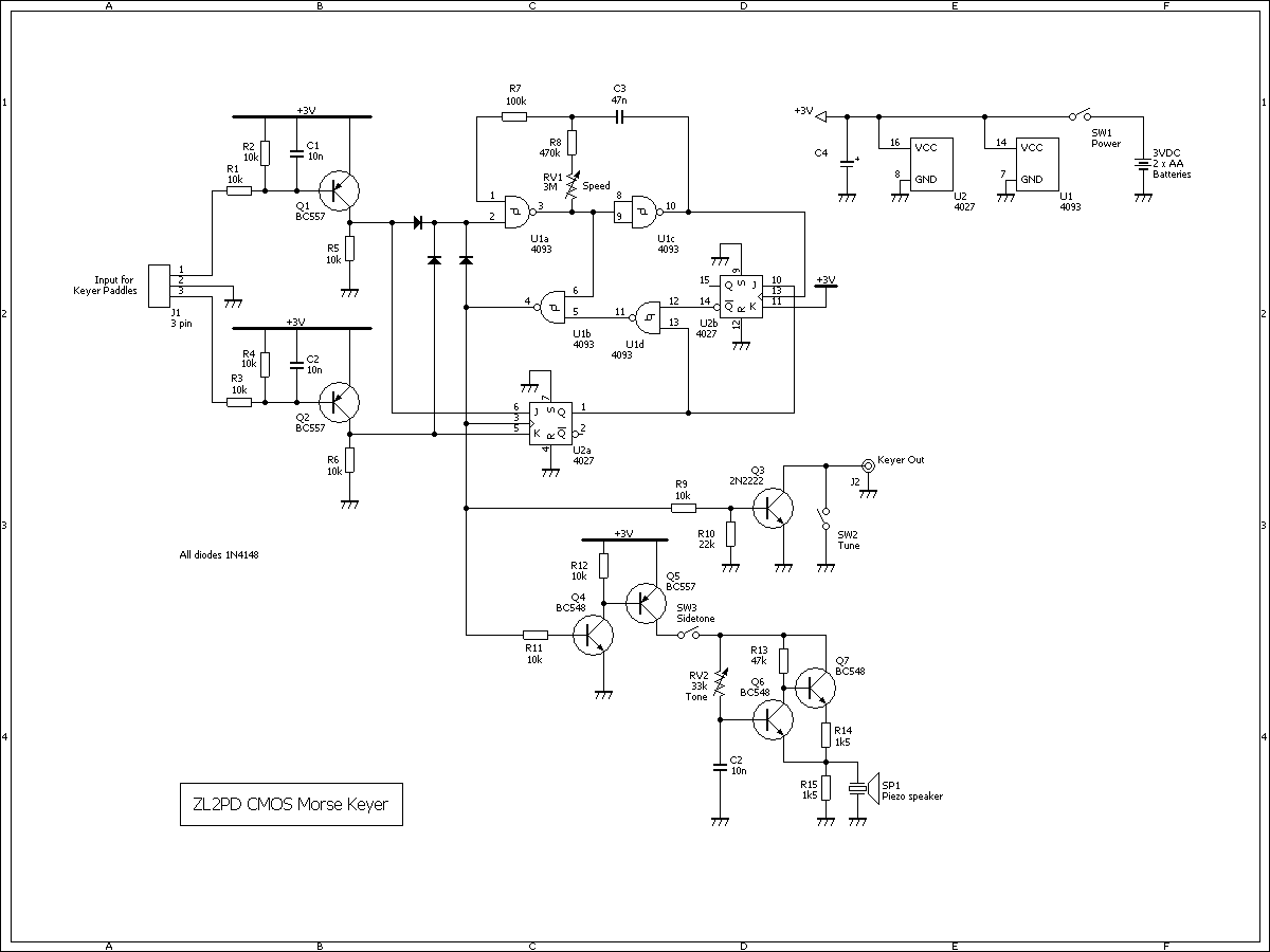
Two inexpensive CMOS integrated circuits and a few transistors were sufficient to convert an old TTL automatic Morse keyer into a low-current, lightweight, battery-powered iambic Morse keyer. Over the last couple of years, the aging Accu-Keyer ceased functioning. This device...

Cmos Pair 2-Mhz Crystal Oscillator
This circuit is a 2 MHz crystal oscillator utilizing a CMOS transistor pair. It is particularly suitable for applications in digital watches and clocks due to its low power consumption. The oscillator is constructed by connecting a CMOS transistor pair...

4081 AND gates
The inputs of the gate must be connected to either LOW or HIGH and must not be left open circuit. This is achieved through the use of input switches along with their pull-down resistors. To prevent loading on the gate's...

Quartz Crystals
The drive level of a crystal unit is indicated by the operating power level or current consumption. Operating the crystal unit at excessive power levels can degrade its characteristics, potentially causing frequency instability or physical failure of the crystal chip....

Light-control electric toy circuit
The light from a flashlight is directed at a phototube, which activates a CMOS logic circuit powered by a battery. This circuit controls the switching action to turn the motor of a model train or other electric toys on or...

CD4013 Push Button CMOS Toggle Flip Flop
The circuit utilizes a CMOS dual D flip-flop (CD4013) to toggle a relay or other load using a momentary push button. Multiple push buttons can be connected in parallel to control the relay from various locations. A high signal from...

A Dozen Small Cmos Alarm Circuits
A selection of small self-contained CMOS alarm circuits is presented. The main features of each alarm are indicated on the circuit diagram itself. All circuits exhibit a very low standby current, making them suitable for battery operation. Each pair of...