


Metronome generator circuit

Description: This is a simple circuit utilizing the NE555 integrated circuit (IC) designed to generate metronomes. Such a circuit is particularly beneficial for music learners. The configuration operates as an astable multivibrator centered around the NE555. The output frequency is determined by the components R1, R2, and C1.
The NE555 timer is a versatile component widely used in various timing applications. In this metronome circuit, it functions in astable mode, continuously oscillating between high and low states to produce a square wave output. The frequency of this output is crucial for generating a consistent beat, which is essential for practice in music.
The resistors R1 and R2, along with the capacitor C1, set the timing interval of the oscillation. The frequency (f) of the output signal can be calculated using the formula:
\[ f = \frac{1.44}{(R1 + 2R2) \cdot C1} \]
Where:
- R1 is connected between the discharge pin (pin 7) and the supply voltage (Vcc).
- R2 is connected from the discharge pin (pin 7) to the threshold pin (pin 6).
- C1 is connected from the threshold pin (pin 6) to ground.
In this configuration, the output frequency can be adjusted by varying the values of R1, R2, and C1, allowing users to set the metronome to their desired tempo.
Additionally, a speaker or piezo buzzer can be connected to the output pin (pin 3) of the NE555 to convert the electrical signal into audible sound. A simple low-pass filter may be integrated to smooth out the signal if necessary, enhancing the sound quality.
This metronome circuit can be powered by a standard DC power supply, typically in the range of 5V to 15V, making it suitable for various applications. The simplicity of the circuit and the low cost of components make it an excellent project for beginners in electronics and music education.Here is a simple circuit using IC NE555 that can be used to generate metronomes. Such a circuit is very useful to those who learns music. The circuit is nothing but an astable multivibrator wired around NE555. The components R1, R2&C1 determines the output frequency.
The NE555 timer is a versatile component widely used in various timing applications. In this metronome circuit, it functions in astable mode, continuously oscillating between high and low states to produce a square wave output. The frequency of this output is crucial for generating a consistent beat, which is essential for practice in music.
The resistors R1 and R2, along with the capacitor C1, set the timing interval of the oscillation. The frequency (f) of the output signal can be calculated using the formula:
\[ f = \frac{1.44}{(R1 + 2R2) \cdot C1} \]
Where:
- R1 is connected between the discharge pin (pin 7) and the supply voltage (Vcc).
- R2 is connected from the discharge pin (pin 7) to the threshold pin (pin 6).
- C1 is connected from the threshold pin (pin 6) to ground.
In this configuration, the output frequency can be adjusted by varying the values of R1, R2, and C1, allowing users to set the metronome to their desired tempo.
Additionally, a speaker or piezo buzzer can be connected to the output pin (pin 3) of the NE555 to convert the electrical signal into audible sound. A simple low-pass filter may be integrated to smooth out the signal if necessary, enhancing the sound quality.
This metronome circuit can be powered by a standard DC power supply, typically in the range of 5V to 15V, making it suitable for various applications. The simplicity of the circuit and the low cost of components make it an excellent project for beginners in electronics and music education.Here is a simple circuit using IC NE555 that can be used to generate metronomes. Such a circuit is very useful to those who learns music. The circuit is nothing but an astable multivibrator wired around NE555. The components R1, R2&C1 determines the output frequency.

frequency conversion circuit composed of NE555
In the circuit, the oscillation frequency of the NE555 is controlled by VT2. When the output at pin 3 is low (during the T1 period), VT1 stops conducting, and VT2 begins to conduct with a current Ic2 flowing through it....

Toggle on off switch
This circuit toggles on and off a NE555 with a single momentary switch. Unlike a mechanical bistable relay the circuit backs to the start condition if you switch off the power supply. No relay contact is used. This circuit could...
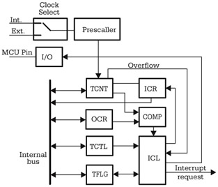
Using the MCU Timers
Although there are significant variations between different implementations of the general-purpose timer in various microcontrollers, many similarities exist in the principles of operation and the structure of the timer subsystem. The central element of the timer subsystem is a counter,...

automatic wiper control
The circuit is built around an astable multivibrator using the NE555 timer. The output at pin 3 remains high for a duration determined by resistor R2 and low for a duration set by resistor R3. The low output pulse activates...
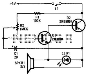
Simple Electronic Metronome
Two complementary transistors create a basic oscillator with a frequency range of approximately 0.5 to several Hz. This circuit serves as a metronome, timer, or pacer for exercise equipment.
The oscillator circuit utilizes a pair of complementary transistors, typically one NPN...
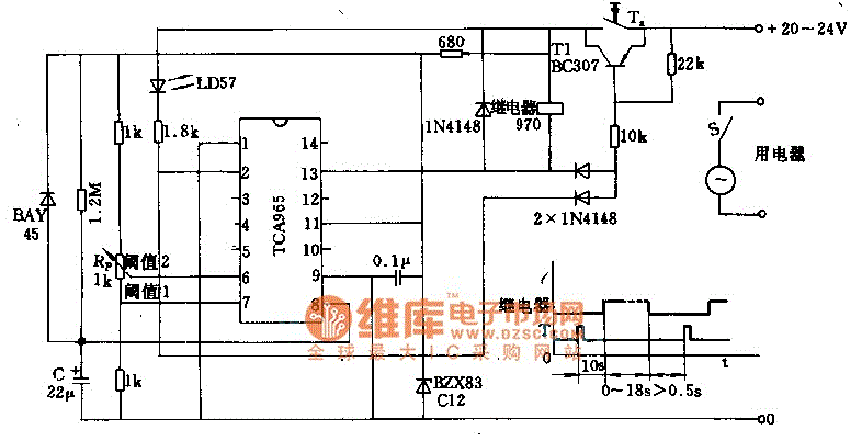
Timer circuit with 106 fixed preset time
The foot 13 between valve value 1 and valve value 2 will draw the transistor base current. If the relay releases, after a recovery time of 0.5 seconds, pressing the key will initiate the switching process again. The timer is...

Timer with alarm
The circuit features two timing ranges: from 10 seconds to 5 minutes and from 1 minute to 80 minutes. It is powered by a 9-V battery. An LED is connected in a manner that allows for a consistent flashing frequency...
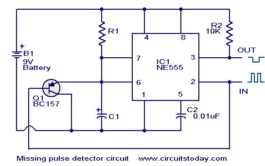
Missing pulse detector circuit using NE555
An NE555 timer integrated circuit (IC) configured in a specific manner can identify the absence of a pulse or an unusually long duration between two successive pulses in a pulse train. Such circuits are applicable for detecting the intermittent operation...

Two Simple 24-Hour Timer Circuit Schematics
These two circuits are multi-range timers that offer periods of up to 24 hours and beyond. They can function as repeating timers or single-shot timers. Both circuits are fundamentally the same, with the primary distinction being their behavior in single-shot...