


Oscillator circuit diagram with triangle-wave/square wave output
#triangle-wave
#square-wave
#comparator
#integrator
#capacitor
#resistor
#limiter circuit
#oscillation frequency
#amplifier

Description: The circuit consists of a lag comparator with amplifier A1 and an inverting integrator A2. The charging and discharging time constant is determined by the integral resistors (R1 + RP1) and the capacitor C1. Diodes VD1 to VD5 form a limiter circuit. The maximum oscillation frequency is influenced by the switching rate of the amplifier. When the switching rate is 10V/µs, to achieve 20V (peak-to-peak).
The described circuit operates as a lag comparator integrated with an inverting integrator, which is essential for generating a specific output waveform in response to input signals. The lag comparator, represented by amplifier A1, is designed to compare input voltage levels and provide a corresponding output that reflects the delay in response. The inverting integrator, represented by amplifier A2, takes the output from the lag comparator and integrates it over time, producing a voltage that is proportional to the integral of the input signal.
The time constants for charging and discharging within this circuit are critically defined by the resistors (R1 and RP1) and the capacitor C1. The total resistance (R1 + RP1) determines how quickly the capacitor can charge and discharge, thereby influencing the overall response time of the circuit. A longer time constant results in a slower response, while a shorter time constant allows for a quicker response to changes in the input signal.
Diodes VD1 to VD5 are configured to form a limiter circuit, which serves to protect the subsequent stages of the circuit from voltage levels that exceed specified thresholds. This limiter circuit ensures that the output waveform remains within safe operating limits, preventing damage to sensitive components and maintaining signal integrity.
The maximum oscillation frequency of the circuit is closely tied to the switching rate of the amplifier. With a switching rate of 10V/µs, the circuit is capable of achieving a peak-to-peak output voltage of 20V. This relationship between switching rate and output voltage is crucial for applications that require rapid signal processing and precise control over voltage levels. The design considerations for this circuit are particularly important in high-speed applications where timing and voltage thresholds must be tightly controlled.The circuit is composed of lag comparator with A1 and inverting integrator A2, and the charging and discharging time constant is decided by integral resistors (R1+RP1) and the capacitor C1. VD1~VD5 form the limiter circuit. The maximum oscillation frequency is related to swicthing rate of amplifier, when swicthing rate is 10V/?
s, in order to get the 20V (p..
The described circuit operates as a lag comparator integrated with an inverting integrator, which is essential for generating a specific output waveform in response to input signals. The lag comparator, represented by amplifier A1, is designed to compare input voltage levels and provide a corresponding output that reflects the delay in response. The inverting integrator, represented by amplifier A2, takes the output from the lag comparator and integrates it over time, producing a voltage that is proportional to the integral of the input signal.
The time constants for charging and discharging within this circuit are critically defined by the resistors (R1 and RP1) and the capacitor C1. The total resistance (R1 + RP1) determines how quickly the capacitor can charge and discharge, thereby influencing the overall response time of the circuit. A longer time constant results in a slower response, while a shorter time constant allows for a quicker response to changes in the input signal.
Diodes VD1 to VD5 are configured to form a limiter circuit, which serves to protect the subsequent stages of the circuit from voltage levels that exceed specified thresholds. This limiter circuit ensures that the output waveform remains within safe operating limits, preventing damage to sensitive components and maintaining signal integrity.
The maximum oscillation frequency of the circuit is closely tied to the switching rate of the amplifier. With a switching rate of 10V/µs, the circuit is capable of achieving a peak-to-peak output voltage of 20V. This relationship between switching rate and output voltage is crucial for applications that require rapid signal processing and precise control over voltage levels. The design considerations for this circuit are particularly important in high-speed applications where timing and voltage thresholds must be tightly controlled.The circuit is composed of lag comparator with A1 and inverting integrator A2, and the charging and discharging time constant is decided by integral resistors (R1+RP1) and the capacitor C1. VD1~VD5 form the limiter circuit. The maximum oscillation frequency is related to swicthing rate of amplifier, when swicthing rate is 10V/?
s, in order to get the 20V (p..
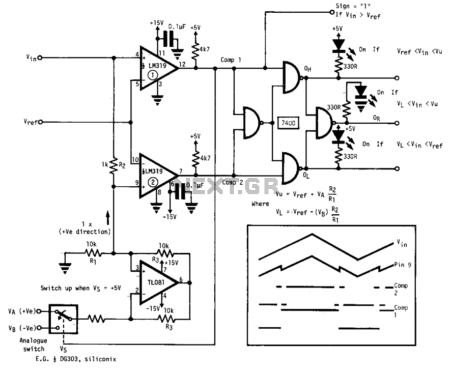
Window comparator
This circuit features independently adjustable upper and lower threshold settings, with digital outputs indicating the sign, within the window range, for both the upper and lower thresholds.
The circuit utilizes two integrated circuits (ICs): the LM319 and the TL081. The LM319...
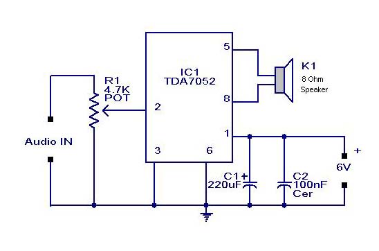
Small or Mini Audio Amplifier Circuit using TDA 7052 IC-Deliver 2 Watts
A compact audio amplifier circuit utilizing the TDA 7052 integrated circuit from Philips. This circuit is suitable for use as a pocket radio amplifier, delivering an output power of 2 watts.
The TDA 7052 is a low-voltage audio amplifier designed specifically...
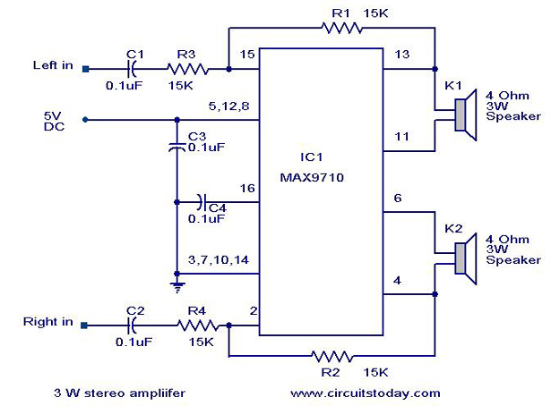
3 W Stereo amplifier using MAX 7910-Audio power amplifier circuit
An audio power amplifier circuit for a 3-watt stereo amplifier using the MAX 7910 IC is explained below.
The audio power amplifier circuit utilizing the MAX 7910 IC is designed to deliver a maximum output power of 3 watts per channel...

5.3W Amplifier With Surround System
The AN7147 Dual 5.3-watt Audio Power Amplifier from Panasonic is categorized as a replacement type, indicating its anticipated availability in the market for an extended period. When combined with additional components, it can be configured to create a simple surround-sound...

The FARA 2 meter amplifier project
This article discusses a 2-meter amplifier capable of delivering an output of 25-30 watts. Over 35 units have been acquired at a cost of less than $50 each in bulk. Photo A displays the final version of the circuit board,...
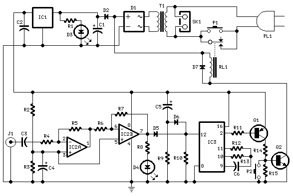
Amplifier Timer
This circuit deactivates an amplifier or other devices when a low-level audio signal at its input is absent for at least 15 minutes. By pressing P1, the device is activated, supplying power to any appliance connected to SK1. The input...

General-Purpose Output Amplifier Circuit
This general-purpose amplifier has a bandwidth of approximately 20 MHz and it uses an LM733/NE592 video amplifier integrated circuit. This circuit can be utilized as a line driver or as a LAN line driver.
The circuit employs the LM733/NE592 video amplifier...

Emitter negative feedback differential amplifier gain control circuit
A controllable gain amplifier functions as an automatic gain control circuit within the execution unit. The primary methods for controlling the amplifier's gain involve two approaches: one is by adjusting certain parameters of the amplifier itself, such as emitter current,...

Suppress Jitter With Hysteresis Circuit
When the comparator's output transitions from low to high, the rising edge of the output pulse, differentiated by the Cl/Rl chain, activates Ql. This action blocks the comparator via its strobing input and maintains its output state for a duration...