


Overtone oscillator with crystal switching
#overtone oscillator
#crystal switching
#inductive phase shift
#frequency compensation
#crystal oscillator
#resonance
#electronic oscillation
#circuit design
#frequency stability
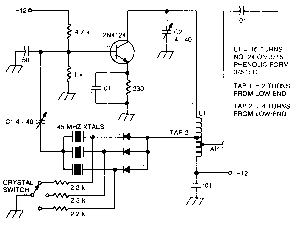
Description: The large inductive phase shift of LI is compensated for by Cl. Overtone crystals have very narrow bandwidth; therefore, the trimmer has a smaller effect than for fundamental-mode operation.
The statement discusses the compensation of inductive phase shifts in a circuit involving an inductor (LI) and a capacitor (Cl). The phase shift introduced by the inductor can significantly affect the performance of the circuit, particularly in resonant applications where precise timing and frequency response are critical. The capacitor is utilized to counterbalance this phase shift, ensuring that the circuit functions correctly within its intended operational parameters.
Additionally, the mention of overtone crystals highlights their application in frequency control and timing circuits. Overtone crystals operate at harmonic frequencies of their fundamental frequency, providing a higher frequency output with a narrower bandwidth. This characteristic makes them suitable for applications requiring high precision. However, the narrower bandwidth also implies that adjustments, such as those made with a trimmer capacitor, will have a reduced impact compared to adjustments made in fundamental-mode operation, where the bandwidth is broader.
In summary, the interaction between the inductor and capacitor is crucial for managing phase shifts, while the use of overtone crystals necessitates careful consideration of bandwidth effects when fine-tuning circuit parameters. This understanding is essential for designing circuits that require accurate frequency control and phase alignment.The large inductive phase shift of LI is compensated for by Cl Overtone crystals have very narrow bandwidth;, the re fore, the trimmer has a smaller effect than for fundamental-mode operation.
The statement discusses the compensation of inductive phase shifts in a circuit involving an inductor (LI) and a capacitor (Cl). The phase shift introduced by the inductor can significantly affect the performance of the circuit, particularly in resonant applications where precise timing and frequency response are critical. The capacitor is utilized to counterbalance this phase shift, ensuring that the circuit functions correctly within its intended operational parameters.
Additionally, the mention of overtone crystals highlights their application in frequency control and timing circuits. Overtone crystals operate at harmonic frequencies of their fundamental frequency, providing a higher frequency output with a narrower bandwidth. This characteristic makes them suitable for applications requiring high precision. However, the narrower bandwidth also implies that adjustments, such as those made with a trimmer capacitor, will have a reduced impact compared to adjustments made in fundamental-mode operation, where the bandwidth is broader.
In summary, the interaction between the inductor and capacitor is crucial for managing phase shifts, while the use of overtone crystals necessitates careful consideration of bandwidth effects when fine-tuning circuit parameters. This understanding is essential for designing circuits that require accurate frequency control and phase alignment.The large inductive phase shift of LI is compensated for by Cl Overtone crystals have very narrow bandwidth;, the re fore, the trimmer has a smaller effect than for fundamental-mode operation.

Crystal-controlled signal source
This general-purpose signal source is highly effective for signal-tracing applications. The output level is adjustable, exceeding 1 Vrms into a 50 Ω load. It is compatible with nearly any crystal in the 1 to 15 MHz frequency range. Q1 operates...

Several gates as a crystal oscillator circuit
The circuit includes several gates arranged as a crystal oscillator circuit. Figure (A) illustrates a crystal oscillator circuit operating at 1 MHz, while Figure (B) depicts a 20 MHz crystal oscillator circuit. Figure (C) represents a variable crystal oscillator circuit...

A crystal-controlled oscillator
A series resonant circuit utilizing a crystal oscillator is illustrated. The crystal impedance reaches a minimum value at the series resonance frequency, resulting in a significant feedback amount. The crystal tuning capacitor (Cc) can slightly adjust the resonance frequency of...

marker generator
A resistor of 100K Ohm is connected between pin 10 and pin 11, while another resistor of 2K Ohm is present in the circuit. The fixed capacitor was determined through trial and error to achieve resonance with the crystal at...

OCXOW-AR1 OCXOW Oven Controlled Crystal Oscillator
The OPB350 series liquid sensor is designed to operate with clear tubes of various outer diameters: 1/16 inch (1.6 mm), 1/8 inch (3.2 mm), 3/16 inch (4.8 mm), and 1/4 inch (6.3 mm). When integrated with output reference circuitry, it...

Crystal Oscillator
A crystal oscillator, particularly a low-frequency variant, can be effectively constructed using an operational amplifier (op-amp) as the amplification component. Below is the schematic diagram of this circuit.
The crystal oscillator circuit utilizes the properties of a quartz crystal to generate...

Crystal oscillator
International Crystal OF-1 LO oscillator circuit for fundamental-mode crystals that you can find.
The International Crystal OF-1 local oscillator (LO) circuit is designed to operate with fundamental-mode crystals, which are widely used in various frequency generation applications. This oscillator circuit typically...

1024kHz and 4kHz square-wave output circuit
The circuit SJT is a 1024 kHz warming crystal oscillator. The circuit is illustrated in the accompanying chart. Due to the low output signal level, a transistor (VT1) is employed as a buffer amplifier. The base bias resistor (R2) of...

Frequency crystal oscillator circuit diagram of 10kHz-150kHz
A transistor in series with capacitor C1 can be utilized to adjust the oscillator output frequency. The frequency may vary with changes in capacitance ranging from 20 pF to 0.01 µF, or as determined by the tuning capacitor. The transistor...