


Sight n sound metronome
#metronome
#unijunction transistor
#speaker
#flashing light
#adjustable frequency
#pulse generator
#audio output
#timing circuit

Description: Precise, adjustable control of beats per minute ranges from a slow tempo of 18 to a rapid tempo of 500. These beats are generated acoustically through a speaker, accompanied by a light that flashes in synchronization. When switch SW1 is closed, capacitor C1 begins to charge through resistors R1 and R2. Eventually, C1 reaches a voltage that activates the emitter of a unijunction transistor, which discharges the energy stored in C1 into an 8-ohm speaker. To produce a distinct "plop" sound, brief pulses across the secondary of transformer T2 drive transistor Q2 into conduction. The additional gain provided by transistors Q3 and Q4 is sufficient to briefly switch relay LI on and off as the pulse wave passes. Capacitor C2 slightly stretches the pulse to counteract the thermal inertia of the lamp, resulting in a bright flash.
The circuit described operates as a beat generator with adjustable tempo, utilizing a unijunction transistor for pulse generation and a speaker for sound output. The primary component responsible for controlling the beat rate is capacitor C1, which charges through the resistors R1 and R2 when the switch SW1 is engaged. The charging process determines the timing of the pulse output, which can be adjusted to achieve a range of tempos.
Once the voltage across C1 reaches a specific threshold, it activates the unijunction transistor, allowing the stored energy to be discharged into the connected speaker. This discharge creates an audible sound, characterized by a "plop" as the energy is released. The transformer T2 plays a crucial role in shaping the pulse waveform, ensuring that it is suitable for driving the subsequent transistor Q2. This transistor amplifies the pulse signal, providing enough current to actuate the relay LI.
Transistors Q3 and Q4 serve to further amplify the signal, ensuring that the relay is effectively switched on and off in response to the pulse waveform. This switching action can be critical for applications that require precise timing or control, such as in light flashing or other timing-dependent circuits. The inclusion of capacitor C2 is significant as it mitigates the effects of thermal inertia in the lamp, allowing for a more pronounced flash when the relay is activated. This design highlights the interplay between various components to achieve a cohesive and responsive electronic system.Precise, adjustable control of beats per minute from a largo of 18 to a frenzied, high presto of 500, These beats are produced acoustically through a speaker. A light flashes at the same rate. When SW1 is closed, CI begins to charge through Rl and R2. Cl will eventually reach a voltage at which the emitter of unijunction transistor is switched on, "dumping" the energy stored in Cl into an 8 ohm speaker.
To produce a distinct "plop", brief pulses across T2 secondary drive Q2 into conduction The extra gain of Q3 and Q4 are sufficient to briefly switch LI on, then o£f; as the pulse wave pas-ses. Capacitor C2 "stretches" the puise slightly to overcome the thermal inertia of the lamp, so that a bright flash occurs,.
The circuit described operates as a beat generator with adjustable tempo, utilizing a unijunction transistor for pulse generation and a speaker for sound output. The primary component responsible for controlling the beat rate is capacitor C1, which charges through the resistors R1 and R2 when the switch SW1 is engaged. The charging process determines the timing of the pulse output, which can be adjusted to achieve a range of tempos.
Once the voltage across C1 reaches a specific threshold, it activates the unijunction transistor, allowing the stored energy to be discharged into the connected speaker. This discharge creates an audible sound, characterized by a "plop" as the energy is released. The transformer T2 plays a crucial role in shaping the pulse waveform, ensuring that it is suitable for driving the subsequent transistor Q2. This transistor amplifies the pulse signal, providing enough current to actuate the relay LI.
Transistors Q3 and Q4 serve to further amplify the signal, ensuring that the relay is effectively switched on and off in response to the pulse waveform. This switching action can be critical for applications that require precise timing or control, such as in light flashing or other timing-dependent circuits. The inclusion of capacitor C2 is significant as it mitigates the effects of thermal inertia in the lamp, allowing for a more pronounced flash when the relay is activated. This design highlights the interplay between various components to achieve a cohesive and responsive electronic system.Precise, adjustable control of beats per minute from a largo of 18 to a frenzied, high presto of 500, These beats are produced acoustically through a speaker. A light flashes at the same rate. When SW1 is closed, CI begins to charge through Rl and R2. Cl will eventually reach a voltage at which the emitter of unijunction transistor is switched on, "dumping" the energy stored in Cl into an 8 ohm speaker.
To produce a distinct "plop", brief pulses across T2 secondary drive Q2 into conduction The extra gain of Q3 and Q4 are sufficient to briefly switch LI on, then o£f; as the pulse wave pas-ses. Capacitor C2 "stretches" the puise slightly to overcome the thermal inertia of the lamp, so that a bright flash occurs,.

Simple metronome
The output of the UJT oscillator is connected to a general-purpose NPN transistor, which drives the speaker. The oscillator's frequency can be adjusted from 15 to 240 beats per minute.
The UJT (Uni-Junction Transistor) oscillator is a relaxation oscillator that generates...

doorphone intercom
An 8-ohm speaker functions as both a microphone and an output device. The BC109C transistor operates in common base mode, providing substantial voltage gain while ensuring a low impedance input suitable for the speaker. Self DC biasing is implemented to...

Speaker Mic Circuit
This circuit enables the use of an inexpensive loudspeaker as a microphone. Sound waves that reach the speaker cone create fluctuations in the voice coil. The movement of the voice coil within the speaker's magnetic field generates a small electrical...
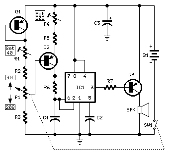
Mini Metronome
Mark the entire scale with the standard metronome steps as follows: 40, 42, 44, 46, 48, 50, 52, 54, 58, 60, 63, 66, 69, 72, 76, 80, 84, 88, 92, 96, 100, 104, 108, 112, 116, 120, 126, 132, 138,...
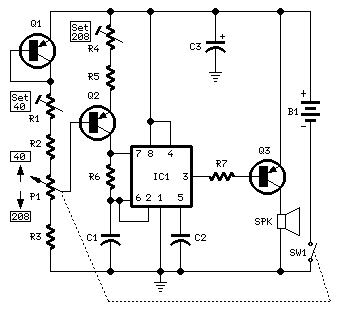
Mini Metronome
Q1 & Q2 provide linear frequency operation of IC1 following P1 resistance variation. Q3 was added in order to obtain a louder click, similar to clockwork metronomes. A 12V micro battery was used to obtain a higher output power and...

Speaker Microphone Schematic
This circuit allows the use of a low-cost loudspeaker as a microphone. Sound waves that reach the speaker cone cause fluctuations in the voice coil. The movement of the voice coil within the speaker's magnetic field generates a small electrical...

Metronome with CA741
This circuit uses a couple of Op-amps to produce an interesting sound effect. The left hand CA741 is wired as a standard astable and produces the timing pulses, controlled by C1, R2 and VR1. The output is fed via C2...

Long-Interval Pulse Generator
A rectangular-wave pulse generator with an extremely long period can be constructed using only two components: a National Semiconductor LM3710 supervisor integrated circuit (IC) and a 100-nF capacitor to suppress noise spikes. This circuit leverages the watchdog and reset timers...
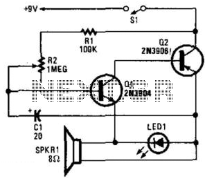
Simple Electronic Metronome
Two complementary transistors create a basic oscillator with a frequency range of approximately 0.5 to several Hz. This circuit serves as a metronome, timer, or pacer for exercise equipment.
The oscillator circuit utilizes a pair of complementary transistors, typically one NPN...