


Simple Wien-Bridge Oscillator
#Wien-bridge
#sine wave
#oscillator
#incandescent lamp
#harmonic distortion
#nonlinear resistance
#signal shaping
#classic circuit

Description: Incandescent lamp has been used to reduce harmonic distortion in sine oscillator circuit. The nonlinear resistance characteristic of the lamp filament help the circuit to shape the signal to approximate the ideal sine wave. Here is the classic Wien-bridge oscillator circuit using the incandescent lamp. More: You can change the frequency of the oscillator by modifying the R1 (and R2), or C1 (and C2).
The described circuit utilizes a Wien-bridge oscillator configuration, which is renowned for generating low-distortion sine waves. In this implementation, an incandescent lamp is strategically integrated into the feedback loop of the oscillator. The nonlinear resistance of the lamp filament plays a crucial role in stabilizing the amplitude of the oscillation. As the voltage across the filament increases, its resistance changes, effectively providing automatic gain control that helps maintain a consistent output amplitude.
The Wien-bridge oscillator consists of a combination of resistors and capacitors that determine the frequency of oscillation. In this case, resistors R1 and R2, as well as capacitors C1 and C2, are pivotal in setting the operational frequency. Modifying the values of these components alters the time constants within the circuit, thus allowing for precise tuning of the output frequency. The relationship governing the frequency (f) of oscillation can be expressed as:
f = 1 / (2πRC)
where R is the equivalent resistance and C is the equivalent capacitance of the circuit.
In practice, the circuit is designed to provide a sine wave output that closely approximates an ideal waveform, minimizing harmonic distortion. This is particularly beneficial in applications where signal purity is critical, such as in audio signal generation or testing. The use of an incandescent lamp not only aids in shaping the output waveform but also introduces a unique characteristic of self-regulation, which can enhance the stability of the oscillator under varying load conditions.
Overall, the Wien-bridge oscillator with an incandescent lamp is an effective solution for applications requiring high-quality sine wave generation, with the added advantage of being easily tunable through component adjustments.Incandescent lamp has been used to reduce harmonic distortion in sine oscillator circuit. The nonlinear resistance characteristic of the lamp filament help the circuit to shape the signal to approximate the ideal sine wave. Here is the classic Wien-bridge oscillator circuit using the incandescent lamp.. You can change the frequency of the oscillator by modifying the R1 (and R2), or C1 (and C2).
The described circuit utilizes a Wien-bridge oscillator configuration, which is renowned for generating low-distortion sine waves. In this implementation, an incandescent lamp is strategically integrated into the feedback loop of the oscillator. The nonlinear resistance of the lamp filament plays a crucial role in stabilizing the amplitude of the oscillation. As the voltage across the filament increases, its resistance changes, effectively providing automatic gain control that helps maintain a consistent output amplitude.
The Wien-bridge oscillator consists of a combination of resistors and capacitors that determine the frequency of oscillation. In this case, resistors R1 and R2, as well as capacitors C1 and C2, are pivotal in setting the operational frequency. Modifying the values of these components alters the time constants within the circuit, thus allowing for precise tuning of the output frequency. The relationship governing the frequency (f) of oscillation can be expressed as:
f = 1 / (2πRC)
where R is the equivalent resistance and C is the equivalent capacitance of the circuit.
In practice, the circuit is designed to provide a sine wave output that closely approximates an ideal waveform, minimizing harmonic distortion. This is particularly beneficial in applications where signal purity is critical, such as in audio signal generation or testing. The use of an incandescent lamp not only aids in shaping the output waveform but also introduces a unique characteristic of self-regulation, which can enhance the stability of the oscillator under varying load conditions.
Overall, the Wien-bridge oscillator with an incandescent lamp is an effective solution for applications requiring high-quality sine wave generation, with the added advantage of being easily tunable through component adjustments.Incandescent lamp has been used to reduce harmonic distortion in sine oscillator circuit. The nonlinear resistance characteristic of the lamp filament help the circuit to shape the signal to approximate the ideal sine wave. Here is the classic Wien-bridge oscillator circuit using the incandescent lamp.. You can change the frequency of the oscillator by modifying the R1 (and R2), or C1 (and C2).

sine/cosine wave oscillator
When an alternating current signal is applied to a capacitor, the phase of the charging current and the voltage across the capacitor shifts by 90 degrees. Conversely, when an alternating current signal is applied to an inductor, the voltage change...
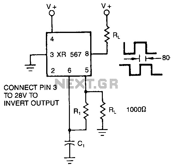
Quadrature-outputs-oscillator
The XR-567 operates as a precision oscillator, providing two distinct square-wave outputs at pins 5 and 8, which are nearly in quadrature phase with one another. Due to the internal biasing configuration, the typical phase shift between the two outputs...

Metal detector 4
The metal detector circuit comprises a detection oscillator, a reference oscillator, a mixer, and a signal display, as illustrated in Figure 8-70. The detection oscillator circuit is made up of the time base oscillator IC1, inductor L1, potentiometer RP1, diode...

Metal detector circuit diagram 8
The metal detector circuit consists of a probe oscillator, a PLL (phase-locked loop) circuit, and an audio alarm circuit. The probe oscillator includes a detection coil (L), transistor (V1), and several resistors (R1 to R3) and capacitors (C1 to C5)....

SINE WAVE TO SQUARE WAVE CONVERTER
This circuit converts a sine wave into a square wave. It consists of a single 2-input NAND Schmitt trigger configured as an inverter, with a trigger level adjustment at its input. As the input voltage exceeds the gate's trigger point,...

Pure Sine Wave Generator
This circuit generates sine waves ranging from 1 kHz to 25 kHz with a total harmonic distortion (THD) of better than -80 dB. It comprises a 4th-order low-pass filter and a TTL counter.
The circuit utilizes a sine wave oscillator to...

The Metal Detector Circuit
This design has not been referred to as a GOLD detector, as that term is reserved for more complex devices capable of distinguishing gold from other metals. There is a significant difference between detecting gold and ordinary metals, known as...

Micro Power AM Broadcast Transmitter
This circuit utilizes a 74HC14 hex Schmitt trigger inverter as a square wave oscillator to drive a small signal transistor configured in a class C amplifier setup. The frequency of the oscillator can be either fixed using a crystal or...

Basic RF Oscillator circuit diagram
Experimenting with the size of the coil and the number of turns can influence the frequency and signal output of the oscillator. The signal can be received using a standard FM radio receiver. The input signal should be coupled via...