


sine wave generator circuit
#sine wave
#operational amplifier
#741
#twin-T filter
#notch filter
#feedback loop
#oscillation
#passive filter

Description: This circuit generates a sine wave using a single operational amplifier (741). The feedback loop of the op-amp includes a twin-T filter connected between its output and inverting input. Positive feedback for oscillation is provided by resistor R2. The twin-T filter is a passive notch filter consisting of two T-networks, with maximum attenuation occurring at the notch frequency fn = 1/(2πRC). One T-network comprises one resistor and two capacitors, while the other includes two resistors and one capacitor. At the notch frequency fn of the twin-T filter, the total phase shift around the loop gain of this op-amp circuit is zero, fulfilling the oscillation condition. Consequently, the circuit produces a sine wave with a frequency equal to fn = 1/(2πRC).
The sine wave generator circuit utilizing a single operational amplifier (741) is an effective design for generating sinusoidal waveforms. The operational amplifier is configured in a negative feedback arrangement with a twin-T notch filter, which is critical for achieving the desired oscillation. The twin-T filter is characterized by its unique configuration of resistors and capacitors, allowing it to create a notch in the frequency response at the specified frequency fn = 1/(2πRC).
In this configuration, one T-network consists of a resistor and two capacitors, while the second T-network is composed of two resistors and one capacitor. This arrangement ensures that at the notch frequency, the phase shift around the feedback loop is precisely zero degrees, which is a necessary condition for sustained oscillation. The resistor R2 is essential in providing the necessary positive feedback to enable the op-amp to oscillate.
The operational amplifier's output, which is a sine wave, can be adjusted for amplitude and frequency by modifying the values of the resistors and capacitors in the twin-T filter. This flexibility makes the circuit suitable for various applications, including signal generation, waveform shaping, and testing of audio equipment. The design is straightforward and cost-effective, leveraging the characteristics of passive components to achieve stable oscillations.
Overall, this sine wave generator circuit is a practical example of using operational amplifiers in waveform generation, demonstrating the fundamental principles of feedback and frequency response in electronic circuit design.This is a circuit for generating a sine wave from a single operational amplifier. The feedback loop of the op amp in this circuit (741) consists of a twin-T filter connected between its output and its inverting input. Positive feedback for oscillation is provided by R2. The twin-T filter (see Figure 2) is a passive notch filter composed of two T-n etworks, with maximum attenuation occurring at fn = 1/(2pRC). One of these T networks has one resistor and two capacitors, while the other has two resistors and one capacitor. At the notch frequency fn of the twin-T filter, the total phase shift around the loop gain of this op amp circuit is zero, which satisfies the requirement for oscillation.
This is why the circuit generates a sine wave with a frequency equal to fn = 1/(2pRC).
The sine wave generator circuit utilizing a single operational amplifier (741) is an effective design for generating sinusoidal waveforms. The operational amplifier is configured in a negative feedback arrangement with a twin-T notch filter, which is critical for achieving the desired oscillation. The twin-T filter is characterized by its unique configuration of resistors and capacitors, allowing it to create a notch in the frequency response at the specified frequency fn = 1/(2πRC).
In this configuration, one T-network consists of a resistor and two capacitors, while the second T-network is composed of two resistors and one capacitor. This arrangement ensures that at the notch frequency, the phase shift around the feedback loop is precisely zero degrees, which is a necessary condition for sustained oscillation. The resistor R2 is essential in providing the necessary positive feedback to enable the op-amp to oscillate.
The operational amplifier's output, which is a sine wave, can be adjusted for amplitude and frequency by modifying the values of the resistors and capacitors in the twin-T filter. This flexibility makes the circuit suitable for various applications, including signal generation, waveform shaping, and testing of audio equipment. The design is straightforward and cost-effective, leveraging the characteristics of passive components to achieve stable oscillations.
Overall, this sine wave generator circuit is a practical example of using operational amplifiers in waveform generation, demonstrating the fundamental principles of feedback and frequency response in electronic circuit design.This is a circuit for generating a sine wave from a single operational amplifier. The feedback loop of the op amp in this circuit (741) consists of a twin-T filter connected between its output and its inverting input. Positive feedback for oscillation is provided by R2. The twin-T filter (see Figure 2) is a passive notch filter composed of two T-n etworks, with maximum attenuation occurring at fn = 1/(2pRC). One of these T networks has one resistor and two capacitors, while the other has two resistors and one capacitor. At the notch frequency fn of the twin-T filter, the total phase shift around the loop gain of this op amp circuit is zero, which satisfies the requirement for oscillation.
This is why the circuit generates a sine wave with a frequency equal to fn = 1/(2pRC).
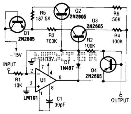
Nonlinear Operational Amplifier Circuit
This operational amplifier circuit utilizes resistor and transistor feedback elements to function as a nonlinear amplifier. The resistors R4 and R6 can be adjusted to modify the breakpoints as needed.
This operational amplifier circuit is designed to operate within the nonlinear...

Long timed circuit diagram LM307N CA3094
The long timer circuit utilizes an operational amplifier, specifically the CA3094, to control the discharge formula for extended timing. This is typically achieved by adjusting the variable resistor RV1, which alters the timing duration to meet specific requirements.
The long timer...

GF2A op amp audio amplifier circuit diagram
The operational amplifier A is utilized in an audio preamplifier circuit. Its advantages include compact size, low noise, low power consumption, and excellent consistency. The operational amplifier can achieve significant negative feedback while increasing output without distortion. The signal distortion...

Adjustable notch filter
In applications where the rejected signal may slightly deviate from the null point in a notch network, it is beneficial to decrease the Q factor of the network. This adjustment ensures consistent rejection across a broader range of input frequencies....

Passive subwoofer filter
The schematic shown does not need any power supply because it is a simple low frequency passive filter. It could be useful if you want to drive an extra subwoofer from your stereo system. The circuit filters the frequency ranges...

Two Op-Amps 60 Hz Notch Filter
A notch filter is a type of filter designed to eliminate a specific frequency component. Ideally, a notch filter targets a single frequency point; however, in practice, it may affect a range of frequencies around the target.
A notch filter, also...

1kHz sine wave oscillator(741)
The circuit illustrated in the diagram is a 1 kHz sine wave oscillator circuit. Based on a double-T circuit configuration, it utilizes a standard 741 operational amplifier to generate a 1000 Hz sine wave output. The circuit begins oscillation when...
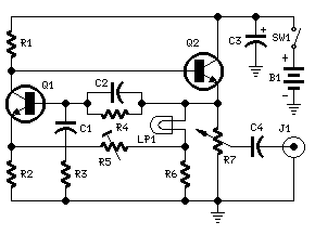
1KHz Sine wave Generator
This circuit generates a good 1KHz sinewave adopting the inverted Wien bridge configuration (C1-R3 & C2-R4). It features a variable output, low distortion and low output impedance in order to obtain good overload capability. A small filament bulb ensures a...

High-performance quadrature sine wave type oscillator circuit
Many RC oscillators utilize advanced circuits within the phase shift unit. These circuits employ voltage feedback amplifiers, whose gain decreases significantly at high frequencies and ceases when high frequency is not attained. The variation in the phase characteristics of the...