


Single Supply Phase Locked LoopCircuit Based On The LM331 IC
#LM331
#phase locked loop
#single supply
#IC
#frequency
#signal processing
#circuit diagram
#electronics
#PLL
#voltage

Description: The following circuit illustrates a Single Supply Phase Locked Loop Circuit Diagram. This circuit is based on the LM331 integrated circuit. Features include the response of...
The Single Supply Phase Locked Loop (PLL) circuit utilizing the LM331 integrated circuit is designed to provide frequency synthesis and signal conditioning in various electronic applications. The circuit operates with a single power supply, making it suitable for battery-operated devices and compact systems where space and power efficiency are critical.
The LM331 is a versatile component that functions as a voltage-to-frequency converter, making it ideal for phase-locked loop applications. The circuit typically includes a reference oscillator, a phase comparator, a loop filter, and a voltage-controlled oscillator (VCO). The reference oscillator generates a stable frequency signal that serves as a comparison input for the phase comparator, which detects the phase difference between the reference signal and the feedback signal from the VCO.
The output of the phase comparator is a pulse-width modulated signal that is filtered by the loop filter. This filter smooths out the fluctuations in the signal, providing a stable control voltage that adjusts the frequency of the VCO. The VCO generates the output frequency, which is then fed back to the phase comparator to maintain phase lock with the reference signal.
Key features of this circuit include its ability to maintain a stable output frequency despite variations in input signal conditions, low power consumption due to the single supply operation, and the capability to operate across a wide range of frequencies. Additionally, the circuit can be fine-tuned by adjusting the values of the passive components in the loop filter, allowing for customization based on specific application requirements.
Overall, the Single Supply Phase Locked Loop Circuit utilizing the LM331 is an effective solution for applications requiring precise frequency control and stability in a compact form factor.The following circuit shows about Single Supply Phase Locked Loop Circuit Diagram. This circuit based on the LM331 IC. Features: the response of ..
The Single Supply Phase Locked Loop (PLL) circuit utilizing the LM331 integrated circuit is designed to provide frequency synthesis and signal conditioning in various electronic applications. The circuit operates with a single power supply, making it suitable for battery-operated devices and compact systems where space and power efficiency are critical.
The LM331 is a versatile component that functions as a voltage-to-frequency converter, making it ideal for phase-locked loop applications. The circuit typically includes a reference oscillator, a phase comparator, a loop filter, and a voltage-controlled oscillator (VCO). The reference oscillator generates a stable frequency signal that serves as a comparison input for the phase comparator, which detects the phase difference between the reference signal and the feedback signal from the VCO.
The output of the phase comparator is a pulse-width modulated signal that is filtered by the loop filter. This filter smooths out the fluctuations in the signal, providing a stable control voltage that adjusts the frequency of the VCO. The VCO generates the output frequency, which is then fed back to the phase comparator to maintain phase lock with the reference signal.
Key features of this circuit include its ability to maintain a stable output frequency despite variations in input signal conditions, low power consumption due to the single supply operation, and the capability to operate across a wide range of frequencies. Additionally, the circuit can be fine-tuned by adjusting the values of the passive components in the loop filter, allowing for customization based on specific application requirements.
Overall, the Single Supply Phase Locked Loop Circuit utilizing the LM331 is an effective solution for applications requiring precise frequency control and stability in a compact form factor.The following circuit shows about Single Supply Phase Locked Loop Circuit Diagram. This circuit based on the LM331 IC. Features: the response of ..

PLL pulse generator(74HC4060 TC9122P)
The PLL pulse generator is illustrated in the accompanying chart. The circuit represents a phase-locked loop (PLL) pulse generator. The PLL generates a fractional frequency from a crystal oscillator, producing a 1 kHz stepped frequency signal. Additionally, it outputs a...

PLL 41MHz reciever with 68HC711D3
The quartz QZ1 of the preceding receivers which set the work frequency is not on the market any more. It is replaced by a locking phase loop allowing the free choice of an unspecified frequency on the band used, either...
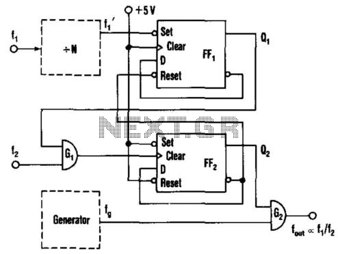
Frequency-Ratio Monitoring Circuit
This circuit generates an output frequency that is linearly proportional to the ratio of two input frequencies. Each pulse of the bias frequency will open a switch for a period equal to half of the second input frequency, allowing a...

Pll receiver
This simple AM circuit utilizes a 561B. It lacks an inductance/capacitance tuning circuit, as the 365 pF capacitor connected between pins 2 and 3 is responsible for all tuning. A good external antenna and a solid ground connection are required...

Positive And Negative Voltage Power Supply
This circuit provides a precision voltage source that can be adjusted to produce zero, positive, and negative voltages, eliminating the need to reverse connections on the power supply. It allows for achieving exactly 0 V without any offset. The circuit...

DECL Documentation
The following describes the design, construction, operation, and use of the DECL (Decade PLL) module. The module incorporates a Phase Locked Loop (PLL) frequency multiplier and a frequency divider to generate various output frequencies based on an input reference frequency....
PLL pulse generator(74HC4060 TC9122P)
The PLL pulse generator is illustrated in the accompanying chart. The circuit represents a phase-locked loop (PLL) pulse generator. The PLL generates a fractional frequency from a crystal oscillator, producing a 1 kHz stepped frequency signal. Additionally, it outputs a...

PLL FM Transmitter Circuit
The PLL transmitter exciter is designed to provide a stable, low noise, frequency-selectable RF signal, which is amplified to a controllable output power sufficient to drive a power amplifier. It utilizes a PLL frequency synthesizer based on the MC145151, covering...

The PLL FM demodulator (4046) circuit
The FM demodulator circuit, as illustrated in the figure, utilizes a 4046 Phase-Locked Loop (PLL) integrated circuit to convert the intermediate frequency FM input signal into a lower frequency output.
The FM demodulator circuit based on the 4046 PLL IC operates...