


Suspended Bicore circuit for robots

Description: The bicore is the basis of advanced BEAM. Most intermediate to advanced BEAM robots are built off of the bicore. Uses go all the way from photovores to servo motor drivers to walkers. What it is is basically just an oscillator whose outputs go (+ -, - +, + -, - +...) and the rate of oscillations is controlled by the resistor (R1). Another cool thing is that they can be grouped together to form large complex structures. R1 controls the rate of oscillation. If you want quick oscillations you use a low value resistor, long oscillations you use a large value resistor. Values below 100K or over 10M are typically not used, with 1.6M being a common value. It has a very wide range of uses including photovores, light-seeking heads, walkers, and servo motor drivers. The walker category is extensive, with configurations ranging from 2 motors to 12 motors, employing no sensors to electronic compasses and sonar. A single bicore cannot perform much beyond blinking a couple of LEDs or driving a motor backward, but they are most effective when used in groups.
The bicore circuit is a fundamental component in the BEAM robotics platform, primarily functioning as an oscillator. The core functionality is derived from its ability to produce alternating signals that can be used to control various robotic functions. The outputs of the bicore oscillate in a specific pattern, which can be described as (+ -, - +, + -, - +). This behavior allows the circuit to drive motors or control LED indicators, depending on the application.
Central to the operation of the bicore is the resistor R1, which dictates the frequency of the oscillations. The choice of resistor value significantly influences the performance characteristics of the circuit. For rapid oscillations, a lower resistor value is preferred, while a higher value results in slower oscillations. It is common practice to select resistor values within the range of 100K to 10M, with 1.6M being a frequently utilized value.
The circuit also incorporates a capacitor, typically a 0.22uF capacitor, which works in conjunction with R1 to stabilize the oscillation frequency and shape the waveform output. The integration of a 74AC240 buffer/driver IC enhances the circuit's capability, allowing for greater control over the output signals and facilitating the driving of larger loads, such as motors.
In practical applications, the bicore can be utilized in a variety of configurations. For instance, in photovores, the oscillating output can be used to control motors that steer toward light sources. Similarly, in robotic walkers, multiple bicore circuits can be combined to coordinate the movement of several motors, enabling complex locomotion patterns. The versatility of the bicore circuit makes it an essential building block for intermediate to advanced BEAM robotics, where multiple units can be interconnected to create sophisticated robotic systems capable of performing a wide range of tasks.The bicore is the basis of advanced BEAM! Most intermediate to advanced BEAM robots are built off of the bicore. Uses go all the way from photovores to servo motor drivers to walkers to.... You get the idea. What it is is basically just an oscillator who's outputs go (+ - , - +, + -, - +....) and the rate of oscillations is controlled by the resister (R1). Another cool thing is that they can be grouped together to form large complex structures. Really a very cool circuit once you figure out how it works. R1 R1 controls the rate of oscillation. If you want quick oscillations you use a low value resister, long oscillations you use large value resister.
I normally don't use values below 100K or over 10M, 1.6M is a common value. As I noted above it has a very wide range of uses. Photovores, light seeking heads, walkers, servo motor drivers.... Just to name a few. The walker category is HUGE!! There's walkers with 2 motors to 12 motors. No sensors to electronic compasses and sonar. A single bicore can't do much other than blink a couple LEDs or make a motor go back (which is sometimes what you might want) but they are most useful in groups. R1 (see circuit notes) 1 Digikey See circuit notes .22uF Capacitor 2 Digikey P4966-ND 74AC240 1 Digikey 74AC240PC-ND
The bicore circuit is a fundamental component in the BEAM robotics platform, primarily functioning as an oscillator. The core functionality is derived from its ability to produce alternating signals that can be used to control various robotic functions. The outputs of the bicore oscillate in a specific pattern, which can be described as (+ -, - +, + -, - +). This behavior allows the circuit to drive motors or control LED indicators, depending on the application.
Central to the operation of the bicore is the resistor R1, which dictates the frequency of the oscillations. The choice of resistor value significantly influences the performance characteristics of the circuit. For rapid oscillations, a lower resistor value is preferred, while a higher value results in slower oscillations. It is common practice to select resistor values within the range of 100K to 10M, with 1.6M being a frequently utilized value.
The circuit also incorporates a capacitor, typically a 0.22uF capacitor, which works in conjunction with R1 to stabilize the oscillation frequency and shape the waveform output. The integration of a 74AC240 buffer/driver IC enhances the circuit's capability, allowing for greater control over the output signals and facilitating the driving of larger loads, such as motors.
In practical applications, the bicore can be utilized in a variety of configurations. For instance, in photovores, the oscillating output can be used to control motors that steer toward light sources. Similarly, in robotic walkers, multiple bicore circuits can be combined to coordinate the movement of several motors, enabling complex locomotion patterns. The versatility of the bicore circuit makes it an essential building block for intermediate to advanced BEAM robotics, where multiple units can be interconnected to create sophisticated robotic systems capable of performing a wide range of tasks.The bicore is the basis of advanced BEAM! Most intermediate to advanced BEAM robots are built off of the bicore. Uses go all the way from photovores to servo motor drivers to walkers to.... You get the idea. What it is is basically just an oscillator who's outputs go (+ - , - +, + -, - +....) and the rate of oscillations is controlled by the resister (R1). Another cool thing is that they can be grouped together to form large complex structures. Really a very cool circuit once you figure out how it works. R1 R1 controls the rate of oscillation. If you want quick oscillations you use a low value resister, long oscillations you use large value resister.
I normally don't use values below 100K or over 10M, 1.6M is a common value. As I noted above it has a very wide range of uses. Photovores, light seeking heads, walkers, servo motor drivers.... Just to name a few. The walker category is HUGE!! There's walkers with 2 motors to 12 motors. No sensors to electronic compasses and sonar. A single bicore can't do much other than blink a couple LEDs or make a motor go back (which is sometimes what you might want) but they are most useful in groups. R1 (see circuit notes) 1 Digikey See circuit notes .22uF Capacitor 2 Digikey P4966-ND 74AC240 1 Digikey 74AC240PC-ND
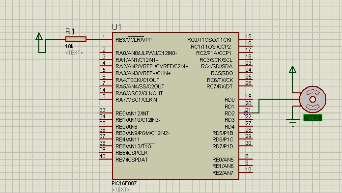
servo motor control with microcontroller
The shaft can be positioned at specific angular positions by sending a coded signal to the servo. As long as the coded signal is present on the input line, the servo will maintain the angular position of the shaft. Changes...

Metal detector circuit diagram 8
The metal detector circuit consists of a probe oscillator, a PLL (phase-locked loop) circuit, and an audio alarm circuit. The probe oscillator includes a detection coil (L), transistor (V1), and several resistors (R1 to R3) and capacitors (C1 to C5)....

Micro Power AM Broadcast Transmitter
This circuit utilizes a 74HC14 hex Schmitt trigger inverter as a square wave oscillator to drive a small signal transistor configured in a class C amplifier setup. The frequency of the oscillator can be either fixed using a crystal or...

Servo Motor Controller Circuit
This is a simple basic design of a servo motor controller with a pulse generator. It utilizes the CMOS IC 7555 in astable mode to generate pulses for driving the motor.
The servo motor controller circuit employs the CMOS IC 7555...

Schematic Diagram Schema HO Train Model Lighthouse Flasher
The aboriginal accessory forms a typical oscillator circuit that produces both a triangle waveform signal and a square wave signal. The triangle signal is fed into a voltage regulator circuit, which converts the triangle voltage signal to a triangle current...
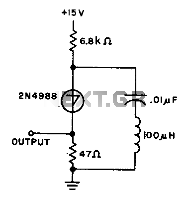
10Khz oscillator
The capacitor charges until the switching voltage is reached. When the switch (SUS) is activated, the inductor causes the current to oscillate. When the current through the switch drops below the holding current, the device turns off, and the cycle...

The door bell circuit
Figure 1 illustrates an economical and straightforward Gate Alarm designed to operate using a small universal AC-DC power supply. IC1a functions as a fast oscillator, while IC1b serves as a slow oscillator. These two oscillators are integrated through IC1c to...

Microcontroller Clocking a Transmitter?
The core of any transmitter is typically an oscillator circuit, and in simple transmitters, such as QRSS devices, a crystal is often used. Frequency adjustment is achieved by modifying the capacitance to ground on one of the crystal's legs. Simple...

Servo Motor Control with PIC16F84
This simple microcontroller circuit regulates a servo motor based on a 3-state switch. The servo motor functions as an actuator with three positions. It consists of three wires: one for VCC, one for ground, and a third for position control....