


Triangular wave generator using Op Amp 741 circuit working and simulated output waveform
#op amp
#741
#triangular wave
#function generator
#square wave
#integrator
#waveform generator
#signal generator
#analog circuit
#operational amplifier

Description: An operational amplifier-based triangular waveform generator is a simple circuit that is widely used in function generators. This circuit utilizes the 741 operational amplifier to create a triangular wave generator. The output waveform of an integrator will be triangular when the input to it is a square wave. Therefore, a triangular wave generator can be constructed by cascading an integrator with a square wave generator, as illustrated in the circuit diagram. This configuration employs two operational amplifiers: the first functions as a comparator, while the second acts as an integrator. A sawtooth waveform can be generated with minor modifications to the triangular wave generator circuit. In this setup, the non-inverting terminal of the second operational amplifier is grounded. To create the sawtooth generator, a potentiometer arrangement is added. One end of the potential divider (R1 and R2) is connected to +Vsat, while the other end connects to the negative-going ramp. When the negative-going ramp reaches a certain value, denoted as Vramp, the effective voltage at point P becomes slightly less than 0V, which switches the output of the comparator to Vsat. During this interval, the output of the integrator generates a positive-going ramp. When this positive-going ramp reaches +Vramp, the voltage at point P becomes slightly greater than 0V, causing the comparator output to switch to +Vsat.
The operational amplifier-based triangular waveform generator employs a fundamental principle of analog signal processing, leveraging the characteristics of operational amplifiers to produce waveforms essential for various applications. The circuit design consists of two main stages: the comparator stage and the integrator stage.
In the comparator stage, the first operational amplifier is configured to compare the input square wave with a reference voltage. The output of this stage toggles between the saturation voltages (+Vsat and -Vsat), creating the square wave that serves as the input for the integrator. The output of the comparator directly influences the charging and discharging cycle of the integrator, leading to the generation of the triangular waveform.
The integrator stage, implemented with the second operational amplifier, integrates the square wave output from the comparator. The integration process converts the square wave into a triangular waveform. The integration time constant, determined by the resistor and capacitor values in the feedback loop of the integrator, dictates the slope of the triangular waveform.
To modify the circuit for generating a sawtooth waveform, the addition of a potentiometer allows for fine-tuning of the ramp characteristics. The potential divider formed by R1 and R2 establishes a reference voltage that influences the comparator's switching threshold. This adjustment enables the circuit to generate a sawtooth waveform by controlling the ramp-up and ramp-down periods effectively.
The design ensures stability and performance across a range of frequencies, making it suitable for applications in signal processing, waveform generation, and testing environments. Careful selection of component values, particularly the feedback resistor and capacitor in the integrator stage, is essential for achieving the desired frequency response and waveform characteristics. Proper power supply decoupling and layout considerations are also critical to minimize noise and ensure reliable operation of the operational amplifiers within the circuit.Operational amplifier based triangular wave form generator is simple circuit that is widely used in function generators. Here is the circuit for Triangular wave generator using 741 op amp. We know that the integrator output waveform will be triangular if the input to it is a square wave. It means that a triangular wave generator can be formed by s imply cascading an integrator and a square wave generator, as illustrated in figure. This circuit uses two operational amplifiers. First op amp functions as a comparator and next op amp as an integrator. Sawtoothwaveform can be easily generated by doing little modifications in the triangular wave generator circuit. In this circuit the non inverting` terminal of second op amp is grounded, to get sawtooth generator we just need to add a potentio meter arrangement.
Thus one end of the potential divider R1 R2 is at +Vsat and other end is at negative going ramp. When the negative going ramp attains a value say Vramp the effective voltage at P becomes slightly less than 0V. This switches output of comparator to Vsat. During this time integrator output will be positive going ramp. When the value of positive going ramp attains +Vramp, voltage at P` becomes slightly greater than 0V, there by switching comparator output to +Vsat.
The operational amplifier-based triangular waveform generator employs a fundamental principle of analog signal processing, leveraging the characteristics of operational amplifiers to produce waveforms essential for various applications. The circuit design consists of two main stages: the comparator stage and the integrator stage.
In the comparator stage, the first operational amplifier is configured to compare the input square wave with a reference voltage. The output of this stage toggles between the saturation voltages (+Vsat and -Vsat), creating the square wave that serves as the input for the integrator. The output of the comparator directly influences the charging and discharging cycle of the integrator, leading to the generation of the triangular waveform.
The integrator stage, implemented with the second operational amplifier, integrates the square wave output from the comparator. The integration process converts the square wave into a triangular waveform. The integration time constant, determined by the resistor and capacitor values in the feedback loop of the integrator, dictates the slope of the triangular waveform.
To modify the circuit for generating a sawtooth waveform, the addition of a potentiometer allows for fine-tuning of the ramp characteristics. The potential divider formed by R1 and R2 establishes a reference voltage that influences the comparator's switching threshold. This adjustment enables the circuit to generate a sawtooth waveform by controlling the ramp-up and ramp-down periods effectively.
The design ensures stability and performance across a range of frequencies, making it suitable for applications in signal processing, waveform generation, and testing environments. Careful selection of component values, particularly the feedback resistor and capacitor in the integrator stage, is essential for achieving the desired frequency response and waveform characteristics. Proper power supply decoupling and layout considerations are also critical to minimize noise and ensure reliable operation of the operational amplifiers within the circuit.Operational amplifier based triangular wave form generator is simple circuit that is widely used in function generators. Here is the circuit for Triangular wave generator using 741 op amp. We know that the integrator output waveform will be triangular if the input to it is a square wave. It means that a triangular wave generator can be formed by s imply cascading an integrator and a square wave generator, as illustrated in figure. This circuit uses two operational amplifiers. First op amp functions as a comparator and next op amp as an integrator. Sawtoothwaveform can be easily generated by doing little modifications in the triangular wave generator circuit. In this circuit the non inverting` terminal of second op amp is grounded, to get sawtooth generator we just need to add a potentio meter arrangement.
Thus one end of the potential divider R1 R2 is at +Vsat and other end is at negative going ramp. When the negative going ramp attains a value say Vramp the effective voltage at P becomes slightly less than 0V. This switches output of comparator to Vsat. During this time integrator output will be positive going ramp. When the value of positive going ramp attains +Vramp, voltage at P` becomes slightly greater than 0V, there by switching comparator output to +Vsat.
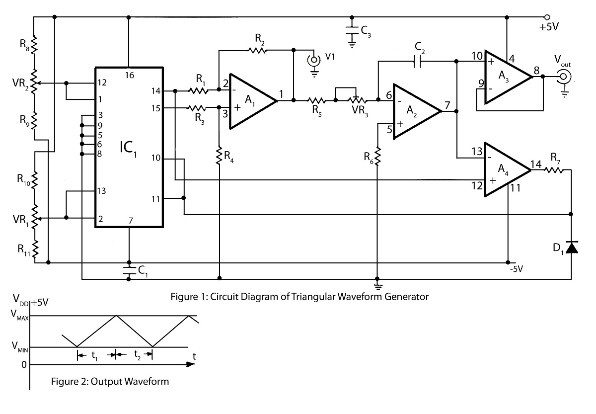
Advanced Triangular wave generator
The triangular wave generator featured on this website offers significant advantages, including a circuit diagram and a detailed description of its operation, focusing on achieving maximum and minimum peak levels of the triangular wave.
The triangular wave generator is an essential...

Function Generator 1
At some point, one may have encountered the function generator in a laboratory setting. By simply adjusting the waveform selector knob, a triangle, square, or sine wave is generated at the output. Another knob allows for the frequency of the...

Function Generator With Lt1016 Circuit
This function generator, based on an LT1016 high-speed comparator, will generate from a single +5-V supply. The slow rate of the op-amps used determines the maximum usable frequency of this circuit.
The function generator utilizes the LT1016 high-speed comparator to produce...

Function generator
The circuit features both square-wave and triangle-wave outputs. The left section operates similarly to a comparator circuit that employs positive feedback for hysteresis. The inverting input is biased at half the Vcc voltage using resistors R4 and R5. The output...
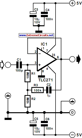
input impedance booster circuit
The input impedance of AC-coupled operational amplifier (op-amp) circuits is primarily determined by the resistance that establishes the DC operating point. When using CMOS op-amps, the input impedance is high, reaching up to 10 MΩ in current op-amps. For applications...

Function Generator with XR2206
For measurement purposes in the electronics laboratory, signals of various frequencies and waveforms are frequently required. A standard function generator typically provides sine, triangular, and square wave outputs. The frequency must be adjustable and should encompass at least the low-frequency...

Subcarrier Adapter For Fm Tuners Circuit
The operational amplifier (Op Amp) U1 and its associated components form a 67-kHz bandpass filter. A twin-T network, consisting of four 1100-ohm resistors and four 0.0022-microfarad capacitors, is integrated into the feedback loop of the op amp. This configuration provides...

Op amp circuit diagram relay delay release
The circuit illustrated in the figure is a delayed release operational amplifier relay circuit. When the power switch is activated, a resistor of 4.7k is connected to the inverting input terminal of the operational amplifier. Additionally, a 10k resistor is...
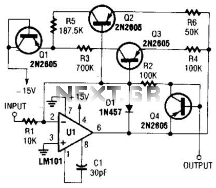
Nonlinear Operational Amplifier Circuit
This operational amplifier circuit utilizes resistor and transistor feedback elements to function as a nonlinear amplifier. The resistors R4 and R6 can be adjusted to modify the breakpoints as needed.
This operational amplifier circuit is designed to operate within the nonlinear...