


Voltage Controlled Oscillator with BF990A
#voltage controlled oscillator
#Hartley oscillator
#varactor diode
#dual-gate FET
#tuning voltage
#frequency modulation
#BF990A
#BB132
#RF circuits
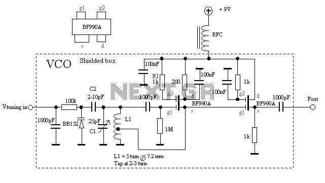
Description: The VCO is based on a Hartley oscillator. The frequency is determined by L1 and capacitor C1. The tuning voltage will change the capacitance in the varactor BB132 which will change the oscillation frequency. The value of capacitor C2 will determine how much the frequency can be changed by the tuning voltage. The larger value, the more the frequency will change. This VCO is based on two dual-gate FETs. The first FET is a Hartley oscillator where the frequency is determined by the value of L1, C1, C2, and the varicap diode. C2 sets the span of the VCO. The second FET is just an amplifier. The gain is less than 1, but the current will be higher, and the oscillator will not be loaded. The output amplitude changes depending on the frequency and how many turns there are on L1. By changing the voltage on g2 at FET1, the amplitude can be set. By adding a resistor to ground, the amplitude will be lowered. In this schematic, g2 is connected to Vcc (through R1), which will give the highest gain. I have made some tests with different coils. The diameter of L1 is the same 7.2mm, but I have changed the turns to 3, 4, and 5. The diagram at the right shows the amplitude and the frequency. You can also see the range of this VCO. During the test, the varicap was removed, so the tuning range is set by C1. The best way to get the oscillator to work is to attach an oscilloscope to the output. If the amplitude of the oscillator is low, the tap point must be moved a bit. The best way is to make 3-4 coils with the tap point at different places and test each coil before deciding which one to use. The amplitude from this VCO is about 200mVRMS at 100MHz.
The Voltage Controlled Oscillator (VCO) described utilizes a Hartley oscillator configuration, which is characterized by its ability to generate oscillations at a frequency determined by the inductance (L1) and capacitance (C1). The inclusion of a varactor diode, specifically the BB132, allows for frequency modulation through the application of a tuning voltage. This tuning voltage alters the capacitance of the varactor, thereby enabling dynamic frequency adjustment.
Capacitor C2 plays a critical role in defining the tuning range of the VCO. By selecting a larger capacitance value for C2, the frequency deviation in response to the tuning voltage is increased, allowing for broader tuning capabilities. The circuit employs two dual-gate FETs; the first functions as the Hartley oscillator, while the second serves as an amplifier. The amplifier FET provides a gain of less than one, but it increases the output current without imposing a load on the oscillator, ensuring stable oscillation.
The output amplitude of the VCO is influenced by both the frequency of oscillation and the number of turns in the inductor L1. Adjustments to the gate voltage (g2) of the first FET can be made to set the desired output amplitude. Additionally, incorporating a resistor to ground can attenuate the output amplitude as needed. The schematic indicates that g2 is connected to Vcc through a resistor (R1), which maximizes gain.
Testing with different coil configurations has demonstrated the impact of inductor turns on performance. The inductor L1 has a consistent diameter of 7.2mm, with variations in the number of turns (3, 4, and 5) evaluated for their effects on amplitude and frequency characteristics. It is noted that during testing, the varactor was temporarily removed, making the tuning range reliant solely on C1.
For optimal performance, connecting an oscilloscope to the output is recommended. Should the oscillator produce a low amplitude signal, adjustments to the tap point on the inductor may be necessary. Constructing multiple coils with varying tap points allows for comparative testing to determine the most effective configuration. The VCO is capable of producing an output amplitude of approximately 200 mVRMS at a frequency of 100 MHz, illustrating its functionality within the desired operational parameters.The VCO is based on a Hartley oscillator. The frequency is determined by L1 and capacitor C1. The Vtuning voltage will change the capacitance in the varactor BB132 wich will change the oscillation-frequency. The value of capacitor C2 will determine how much the frequency can be changed by the tuning voltage.
The larger value the more the frequency will change. This VCO is based on two dual-gate FET. First FET is a Hartley oscillator where the frequency is determined by the value of L1, C1, C2 and the varicap diod. C2 set the span of the VCO. The second FET is just an amplifier. The gain is less than 1, but the current will be higher and the oscillator will not be loaded. The output amplitud changes depending on the frequency and how many turns there is on L1. By changing the voltage on g2 at FET1 you can set the amplitud. By adding a resistor to ground you will lower the amplitud. In this schematic I have conected g2 to Vcc (through R1) wich will give the highest gain. I have made some test with different coils. The diameter of L1 is the same 7.2mm but I have changed the turns to 3, 4 and 5. The diagram at the right shows the Amplitud and the frequency. You can also se the range of this VCO. During the test the varicap was removed so the tuning range is set by C1. The best way to get the oscillator work is to attach a oscilloscop to the output. If the amplitud of the oscillator is low, you must move the tap-point a bit. The best way is to make 3-4 coils with the tap-point at different places and test each coil before you decide wich one you will use. The amplitud from my VCO is about 200mVRMS at 100MHz.
The Voltage Controlled Oscillator (VCO) described utilizes a Hartley oscillator configuration, which is characterized by its ability to generate oscillations at a frequency determined by the inductance (L1) and capacitance (C1). The inclusion of a varactor diode, specifically the BB132, allows for frequency modulation through the application of a tuning voltage. This tuning voltage alters the capacitance of the varactor, thereby enabling dynamic frequency adjustment.
Capacitor C2 plays a critical role in defining the tuning range of the VCO. By selecting a larger capacitance value for C2, the frequency deviation in response to the tuning voltage is increased, allowing for broader tuning capabilities. The circuit employs two dual-gate FETs; the first functions as the Hartley oscillator, while the second serves as an amplifier. The amplifier FET provides a gain of less than one, but it increases the output current without imposing a load on the oscillator, ensuring stable oscillation.
The output amplitude of the VCO is influenced by both the frequency of oscillation and the number of turns in the inductor L1. Adjustments to the gate voltage (g2) of the first FET can be made to set the desired output amplitude. Additionally, incorporating a resistor to ground can attenuate the output amplitude as needed. The schematic indicates that g2 is connected to Vcc through a resistor (R1), which maximizes gain.
Testing with different coil configurations has demonstrated the impact of inductor turns on performance. The inductor L1 has a consistent diameter of 7.2mm, with variations in the number of turns (3, 4, and 5) evaluated for their effects on amplitude and frequency characteristics. It is noted that during testing, the varactor was temporarily removed, making the tuning range reliant solely on C1.
For optimal performance, connecting an oscilloscope to the output is recommended. Should the oscillator produce a low amplitude signal, adjustments to the tap point on the inductor may be necessary. Constructing multiple coils with varying tap points allows for comparative testing to determine the most effective configuration. The VCO is capable of producing an output amplitude of approximately 200 mVRMS at a frequency of 100 MHz, illustrating its functionality within the desired operational parameters.The VCO is based on a Hartley oscillator. The frequency is determined by L1 and capacitor C1. The Vtuning voltage will change the capacitance in the varactor BB132 wich will change the oscillation-frequency. The value of capacitor C2 will determine how much the frequency can be changed by the tuning voltage.
The larger value the more the frequency will change. This VCO is based on two dual-gate FET. First FET is a Hartley oscillator where the frequency is determined by the value of L1, C1, C2 and the varicap diod. C2 set the span of the VCO. The second FET is just an amplifier. The gain is less than 1, but the current will be higher and the oscillator will not be loaded. The output amplitud changes depending on the frequency and how many turns there is on L1. By changing the voltage on g2 at FET1 you can set the amplitud. By adding a resistor to ground you will lower the amplitud. In this schematic I have conected g2 to Vcc (through R1) wich will give the highest gain. I have made some test with different coils. The diameter of L1 is the same 7.2mm but I have changed the turns to 3, 4 and 5. The diagram at the right shows the Amplitud and the frequency. You can also se the range of this VCO. During the test the varicap was removed so the tuning range is set by C1. The best way to get the oscillator work is to attach a oscilloscop to the output. If the amplitud of the oscillator is low, you must move the tap-point a bit. The best way is to make 3-4 coils with the tap-point at different places and test each coil before you decide wich one you will use. The amplitud from my VCO is about 200mVRMS at 100MHz.

VFO/BUFFER circuit
It is essentially a standard Hartley oscillator, with an output of +7 dBm into 50 Ohms. It is advised against adding a gate diode, as this circuit does not require it and such an addition would degrade phase noise performance,...

MFOS NOISE TOASTER Lo-Fi Noise Box
The MFOS Noise Toaster circuit comprises seven primary components: a voltage-controlled oscillator (VCO), a white noise generator, a voltage-controlled low-pass filter, a low-frequency oscillator (LFO), a simple attack-release (AR) envelope generator, a simple voltage-controlled amplifier (VCA), and a one-watt amplifier...

Hartley oscillator requires no coupled inductors
Examine a traditional Hartley oscillator circuit, and you'll note its trademark: a tapped inductor that determines the frequency of oscillation and provides oscillation-sustaining feedback. Although you can easily calculate the total inductance required for a given frequency, finding the coupling...
Methods of frequency modulation
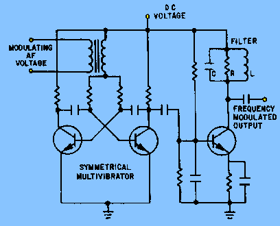
The circuit depicted in figure 2-6 and discussed in previous sections serves illustrative purposes only and is not practical in real-world applications. Nevertheless, the fundamental principle involved—the variation in reactance of an oscillator circuit in response to modulating voltage—represents one...

Three-point oscillator inductor
A three-point oscillator, also known as a Hartley oscillator, is similar to the Colpitts oscillator; however, its feedback circuit consists of two series inductors and a capacitor.
The three-point oscillator is a type of electronic oscillator that generates sine waves. It...

hartley oscillators
Hartley oscillators are inductively coupled, variable frequency oscillators that can be series or shunt fed. They feature a center-tapped inductor and a tuning capacitor, which simplifies the circuit construction. The schematic includes a buffer stage and an amplifier stage designed...

Varactor or varicap Diode
A summary of the varactor or varicap diode used in many radio frequency circuits to provide an electronically variable capacitance.
Varactor diodes, also known as varicap diodes, are semiconductor devices that exploit the voltage-dependent capacitance of a reverse-biased p-n junction. These...

electronic canary
A modified Hartley oscillator can be utilized to attract new friends or serve as a replacement doorbell.
The modified Hartley oscillator is a type of LC oscillator that uses an inductor-capacitor (LC) circuit to generate a continuous wave signal. This oscillator...

Electronic Canary circuit
This modified Hartley oscillator can be utilized to attract new friends or serve as a replacement doorbell.
The modified Hartley oscillator is a type of electronic oscillator that generates a continuous waveform, typically a sine wave, using an LC (inductor-capacitor) circuit....