


0-20V 3A bench PSU

Description: It is too late to calculate Ohm's Law accurately, but based on the information provided, a 24V/2A supply should dissipate approximately 1.88W in a 0.47-ohm resistor and 4W in a 0.1-ohm resistor. The LM723 chip is not recommended. The Fairchild UA723, one of the earliest analog integrated circuits released nearly 50 years ago, has suboptimal performance. It shares its era with the UA709 operational amplifier, which is also outdated. The gain of the 723 is limited, making it an ineffective regulator, and it cannot be adjusted below 2V. Designing a power supply with this chip would require considerable effort for a device that cannot regulate down to 0V. The current limit of the 723 is crude and tends to drift as the supply heats up. A power supply functioning as a stable current source is beneficial. The 2N3055 transistor requires an efficient heatsink to dissipate power; thus, using multiple 2N3055 devices with 0.1-ohm emitter resistors, as seen in the 723 circuit, is advisable instead of a single 2N3055. A substantial passive heatsink or a capable CPU cooler is necessary to manage the power. The driver transistor should also be mounted on a heatsink. The DIY design can regulate down to 0V, features a quality current limit, and possesses higher gain for better DC regulation, along with appropriate frequency compensation. Power-on transients appear to be addressed in this design. Although the LM723 chip is usable, the DIY design is likely superior, making it worth the additional effort. Although the 723 circuit may seem simpler, constructing a case, heatsink, large transformer, meters, switches, and potentiometers is a more significant undertaking than adding a few extra components. Investing effort into a supply that cannot power a 1.5V device is impractical. Attached are datasheets for single-output 1-5A power supplies and one with two outputs, which have been saved for further research. They seem acceptable, albeit slightly more complex on the control side due to the use of buttons connected to a digital potentiometer. Modifying the design to include a standard ten-turn potentiometer and replacing the custom LCD with a microcontroller or another multimeter chip with a 7-segment display (such as the ICL7106, which has an LCD display driver, or the ICL7107, which drives seven-segment digits directly) should be straightforward. If making a PCB is a hindrance, it is possible to build a reliable controller on veroboard or stripboard, with the option to create a neater PCB regulator board later. A stripboard controller can be functional and reliable, and can be assembled within a day. The critical aspect will be obtaining an adequate heatsink, likely costing at least $20-$30.
The design of a power supply utilizing the LM723 chip presents significant limitations that can impact performance and usability. The inability to adjust below 2V restricts the versatility of the power supply, particularly for applications requiring lower voltages. The crude current limiting feature of the LM723 poses a risk of instability, especially as temperature variations occur during operation.
In contrast, a DIY power supply design, utilizing multiple 2N3055 transistors with 0.1-ohm emitter resistors, offers improved thermal management and current regulation capabilities. The parallel configuration of transistors enhances the overall current handling capacity while distributing heat more effectively across multiple devices. This configuration requires careful consideration of the heatsinking solution, ensuring adequate thermal dissipation to maintain reliable operation.
The incorporation of a higher gain regulator in the DIY design contributes to enhanced DC regulation, allowing for more precise voltage output. Proper frequency compensation is critical to prevent oscillations and ensure stable operation across varying load conditions. Additionally, addressing power-on transients can prevent potential damage to connected loads and improve the overall reliability of the supply.
For the control interface, utilizing a digital potentiometer in conjunction with a microcontroller or a dedicated multimeter chip provides flexibility in user interaction. This approach allows for more precise voltage adjustments and the potential for digital readouts, enhancing user experience. The integration of a ten-turn potentiometer can further improve resolution in voltage settings, making the power supply adaptable to a variety of applications.
In summary, while the LM723 may serve as a basic regulator, the DIY approach offers significant advantages in terms of performance, flexibility, and reliability. The additional effort required in design and assembly is justified by the superior capabilities of a well-engineered power supply. The outlined considerations regarding heatsinking, component selection, and user interface design are essential for achieving a functional and efficient power supply that can meet a wide range of operational demands.It`s a little late to calculate ohm`s law right now, as far as I can see 24V/2A should dissipate 1, 88W in the 0, 47 ohm resistor and 4W in the 0, 1 ohm resistor. I wouldn`t use the Lm723 chip. The Fairchild uA723 was amongst the earliest analog ICs - it iwas released almost 50 years ago and the performance is not great.
It is the same vintage as the uA709 opamp and be very greatful you will never have to use a uA709. The 723 gain is limited so it is not a great regulator, and you cannot adjust down below 2v. If you are going to build a power supply, it is far too much effort to end up with a fairly poor supply that cannot regulate to 0V. The 723 current limit is very crude and it will drift noticeably as the supply warms up. The use of a power supply as a stable current source is a very useful feature. It takes a really good heatsink to dissipate the power in the 2N3055 and so I would recommend multiple 2N3055 devices with 0.
1 ohm emitter resistors (as in the 723 circuit) to replace a single 2N3055. You will need either a big passive heatsink, or a good CPU cooler can handle the power as well. The driver transistor needs to be on a heatsink as well. The DIY design does go down to 0V, it does have a good quality current limit, it has a much higher gain regulator so you will get better DC regulation, it looks like it has proper frequency compensation. It looks like power on transients has been considered. I think it is probably not a bad design at all. I wouldn`t use the Lm723 chip. The Fairchild uA723 was amongst the earliest analog ICs - it iwas released almost 50 years ago and the performance is not great.
It is the same vintage as the uA709 opamp and be very greatful you will never have to use a uA709. It would be useable, but the diy design is probably so much better that it is worth the effort. The 723 circuit looks simpler, but building a case, heatsink, mounting a big transformer, meters, switches, potentiometers, etc is a far bigger task then a few extra components. To put all that work into a supply that couldn`t be used to power a 1. 5v device is nuts. It would be useable, but the diy design is probably so much better that it is worth the effort. The 723 circuit looks simpler, but building a case, heatsink, mounting a big transformer, meters, switches, potentiometers, etc is a far bigger task then a few extra components.
To put all that work into a supply that couldn`t be used to power a 1. 5v device is nuts. For example, I`m attaching the datasheets they had for single output, 1-5 a power supplies and one with 2 outputs. i`ve saved them to do my own research on the designs. They look ok to my "untrained` eye, just slightly more complex on the control side due to using buttons on the front coupled with a digital potentiometer.
If you tweak the design to use a standard ten turn pot and replace the custom lcd with your own mcu or another multimeter chip with 7 segment display (they use icl7106 which has lcd display driver, icl7107 is available and drives seven segment digits directly and there`s even ready made boards on ebay) so it should be easy to make them. It would be useable, but the diy design is probably so much better that it is worth the effort. The 723 circuit looks simpler, but building a case, heatsink, mounting a big transformer, meters, switches, potentiometers, etc is a far bigger task then a few extra components.
To put all that work into a supply that couldn`t be used to power a 1. 5v device is nuts. If making a PCB slows you down, don`t. You can build a perfectly good controller on veroboard/stripboard and at any time in the future, you can make a neater PCB regulator board to replace it. A stripboard controller though can be completely reliable and functional and you can put it together easily in a day.
The key will be the case, getting an adequate heatsink (you probably need one costing $20-$30 at least). The thing about power supplie
The design of a power supply utilizing the LM723 chip presents significant limitations that can impact performance and usability. The inability to adjust below 2V restricts the versatility of the power supply, particularly for applications requiring lower voltages. The crude current limiting feature of the LM723 poses a risk of instability, especially as temperature variations occur during operation.
In contrast, a DIY power supply design, utilizing multiple 2N3055 transistors with 0.1-ohm emitter resistors, offers improved thermal management and current regulation capabilities. The parallel configuration of transistors enhances the overall current handling capacity while distributing heat more effectively across multiple devices. This configuration requires careful consideration of the heatsinking solution, ensuring adequate thermal dissipation to maintain reliable operation.
The incorporation of a higher gain regulator in the DIY design contributes to enhanced DC regulation, allowing for more precise voltage output. Proper frequency compensation is critical to prevent oscillations and ensure stable operation across varying load conditions. Additionally, addressing power-on transients can prevent potential damage to connected loads and improve the overall reliability of the supply.
For the control interface, utilizing a digital potentiometer in conjunction with a microcontroller or a dedicated multimeter chip provides flexibility in user interaction. This approach allows for more precise voltage adjustments and the potential for digital readouts, enhancing user experience. The integration of a ten-turn potentiometer can further improve resolution in voltage settings, making the power supply adaptable to a variety of applications.
In summary, while the LM723 may serve as a basic regulator, the DIY approach offers significant advantages in terms of performance, flexibility, and reliability. The additional effort required in design and assembly is justified by the superior capabilities of a well-engineered power supply. The outlined considerations regarding heatsinking, component selection, and user interface design are essential for achieving a functional and efficient power supply that can meet a wide range of operational demands.It`s a little late to calculate ohm`s law right now, as far as I can see 24V/2A should dissipate 1, 88W in the 0, 47 ohm resistor and 4W in the 0, 1 ohm resistor. I wouldn`t use the Lm723 chip. The Fairchild uA723 was amongst the earliest analog ICs - it iwas released almost 50 years ago and the performance is not great.
It is the same vintage as the uA709 opamp and be very greatful you will never have to use a uA709. The 723 gain is limited so it is not a great regulator, and you cannot adjust down below 2v. If you are going to build a power supply, it is far too much effort to end up with a fairly poor supply that cannot regulate to 0V. The 723 current limit is very crude and it will drift noticeably as the supply warms up. The use of a power supply as a stable current source is a very useful feature. It takes a really good heatsink to dissipate the power in the 2N3055 and so I would recommend multiple 2N3055 devices with 0.
1 ohm emitter resistors (as in the 723 circuit) to replace a single 2N3055. You will need either a big passive heatsink, or a good CPU cooler can handle the power as well. The driver transistor needs to be on a heatsink as well. The DIY design does go down to 0V, it does have a good quality current limit, it has a much higher gain regulator so you will get better DC regulation, it looks like it has proper frequency compensation. It looks like power on transients has been considered. I think it is probably not a bad design at all. I wouldn`t use the Lm723 chip. The Fairchild uA723 was amongst the earliest analog ICs - it iwas released almost 50 years ago and the performance is not great.
It is the same vintage as the uA709 opamp and be very greatful you will never have to use a uA709. It would be useable, but the diy design is probably so much better that it is worth the effort. The 723 circuit looks simpler, but building a case, heatsink, mounting a big transformer, meters, switches, potentiometers, etc is a far bigger task then a few extra components. To put all that work into a supply that couldn`t be used to power a 1. 5v device is nuts. It would be useable, but the diy design is probably so much better that it is worth the effort. The 723 circuit looks simpler, but building a case, heatsink, mounting a big transformer, meters, switches, potentiometers, etc is a far bigger task then a few extra components.
To put all that work into a supply that couldn`t be used to power a 1. 5v device is nuts. For example, I`m attaching the datasheets they had for single output, 1-5 a power supplies and one with 2 outputs. i`ve saved them to do my own research on the designs. They look ok to my "untrained` eye, just slightly more complex on the control side due to using buttons on the front coupled with a digital potentiometer.
If you tweak the design to use a standard ten turn pot and replace the custom lcd with your own mcu or another multimeter chip with 7 segment display (they use icl7106 which has lcd display driver, icl7107 is available and drives seven segment digits directly and there`s even ready made boards on ebay) so it should be easy to make them. It would be useable, but the diy design is probably so much better that it is worth the effort. The 723 circuit looks simpler, but building a case, heatsink, mounting a big transformer, meters, switches, potentiometers, etc is a far bigger task then a few extra components.
To put all that work into a supply that couldn`t be used to power a 1. 5v device is nuts. If making a PCB slows you down, don`t. You can build a perfectly good controller on veroboard/stripboard and at any time in the future, you can make a neater PCB regulator board to replace it. A stripboard controller though can be completely reliable and functional and you can put it together easily in a day.
The key will be the case, getting an adequate heatsink (you probably need one costing $20-$30 at least). The thing about power supplie
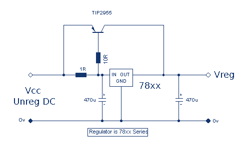
Increasing Regulator Current
Although the 78xx series of voltage regulators are available with different current outputs, you can boost the available current output with this circuit. A power transistor is used to supply extra current to the load, maintaining a constant voltage. Currents...

stabilizer circuit
This circuit functions as a high-quality power supply with a continuously variable stabilized output that can be adjusted to any value between 0 and 30 VDC. It includes an electronic output current limiter that effectively regulates the output current from...

LM78S40 5V to 15V Step-up Voltage Regulator
A step-up conversion can be achieved without utilizing a transformer. This circuit is capable of converting a 5V DC source into 15V. It is important to note that there is no power gain.
The described circuit employs a DC-DC boost converter...

Adjustable output voltage power supply circuit MAX610
The output voltage can be calculated as follows: U = 1.3 (1 + R3 / R4) (V), where R3 and R4 are part of an adjustment potentiometer, allowing for a continuously adjustable output voltage.
The described circuit involves a voltage output...

5 A stabilized power supply
This is a simple but powerful nutrition that less than 5 A can deliver. The circuit works by using a normal type 78xx voltage regulator and a buffer transistor. When the output current over 200 mA, then take over the...

Shortcircuit protected voltage regulator
At this voltage regulator prototype the maximum current, with output shortcircuited it was only 0.5 A, so no overheating occurred. In this DC voltage regulator circuit, T1 is for current limitation. As soon as the voltage on the R2 +...

Automobile-voltage-regulator
A monolithic 555-type timer serves as the core component of this straightforward automobile voltage regulator. When the timer is inactive, resulting in a low output at pin 3, the power Darlington transistor pair remains off. If the battery voltage drops...

Temperature compensation of the symmetrical power supply 7812 F007C
The circuit is a temperature-compensated power supply that generates a negative voltage to track positive voltage changes in a symmetrical voltage integrated power supply. It features a three-terminal regulator connected with two identical transistors, leveraging the temperature characteristics of the...

Regulator Combination Circuits
There are a number of ways to obtain the low voltages required to run small projects from the wall power outlet. The simplest way is to buy a factory-built molded supply which is designed to plug directly into the wall...