


0-30 Volt Laboratory Power Supply
#laboratory power supply
#linear power supply
#voltage regulator
#constant current
#op-amp feedback
#transistor regulator
#battery charging
#0-30V
#1A

Description: The linear power supply, shown in the schematic, provides 0-30 volts, at 1 amp, maximum, using a discrete transistor regulator with op-amp feedback to control the output voltage. The supply was constructed in 1975 and has a constant current mode that is used to recharge batteries. More: A more modern circuit might use a single IC regulator, such as the MC78XX, or MC79XX series, immediately after the half wave rectifier, to replace approximately 30 components, or at least a high precision zener diode to replace D10 as the voltage reference.
The linear power supply circuit is designed to deliver a regulated output voltage ranging from 0 to 30 volts at a maximum load current of 1 amp. The core of the circuit utilizes a discrete transistor as a linear regulator, which is complemented by an operational amplifier (op-amp) that provides feedback for voltage regulation. This feedback mechanism ensures that variations in load do not significantly affect the output voltage, maintaining a stable supply for sensitive electronic applications.
The circuit architecture begins with an AC input, which is first processed by a half-wave rectifier. This rectification stage converts the AC voltage into a pulsating DC voltage. The rectified output is then smoothed using capacitors to reduce ripple voltage, providing a more stable DC input for the subsequent regulation stage.
The discrete transistor, configured as a linear regulator, is responsible for adjusting the output voltage based on the feedback received from the op-amp. The op-amp compares the output voltage with a reference voltage and adjusts the base current of the transistor accordingly. This configuration allows for precise control of the output voltage, making it suitable for applications such as battery charging, where a constant voltage is critical.
In addition to the primary regulation function, the power supply features a constant current mode, which is particularly useful for recharging batteries. In this mode, the circuit can limit the output current to a predetermined value, preventing overcurrent conditions that could damage the battery.
While the original design dates back to 1975, modern advancements in technology suggest alternatives that could simplify the circuit. For instance, integrating a single IC regulator from the MC78XX or MC79XX series immediately after the half-wave rectifier could significantly reduce the component count from approximately 30 to a more manageable number. This integration not only streamlines the design but also enhances reliability and performance. Additionally, replacing the discrete voltage reference diode (D10) with a high-precision zener diode can improve voltage stability and accuracy.
Overall, this linear power supply circuit exemplifies a robust design that balances simplicity and functionality, making it a valuable tool for various electronic applications.The linear power supply, shown in the schematic, provides 0-30 volts, at 1 amp, maximum, using a discrete transistor regulator with op-amp feedback to control the output voltage. The supply was constructed in 1975 and has a constant current mode that is used to recharge batteries.
A more modern circuit might use a single IC regulator, such as the MC78XX, or MC79XX series, immediately after the half wave rectifier, to replace approximately 30 components, or at least a high precision zener diode to replace D10 as the voltage referenc
The linear power supply circuit is designed to deliver a regulated output voltage ranging from 0 to 30 volts at a maximum load current of 1 amp. The core of the circuit utilizes a discrete transistor as a linear regulator, which is complemented by an operational amplifier (op-amp) that provides feedback for voltage regulation. This feedback mechanism ensures that variations in load do not significantly affect the output voltage, maintaining a stable supply for sensitive electronic applications.
The circuit architecture begins with an AC input, which is first processed by a half-wave rectifier. This rectification stage converts the AC voltage into a pulsating DC voltage. The rectified output is then smoothed using capacitors to reduce ripple voltage, providing a more stable DC input for the subsequent regulation stage.
The discrete transistor, configured as a linear regulator, is responsible for adjusting the output voltage based on the feedback received from the op-amp. The op-amp compares the output voltage with a reference voltage and adjusts the base current of the transistor accordingly. This configuration allows for precise control of the output voltage, making it suitable for applications such as battery charging, where a constant voltage is critical.
In addition to the primary regulation function, the power supply features a constant current mode, which is particularly useful for recharging batteries. In this mode, the circuit can limit the output current to a predetermined value, preventing overcurrent conditions that could damage the battery.
While the original design dates back to 1975, modern advancements in technology suggest alternatives that could simplify the circuit. For instance, integrating a single IC regulator from the MC78XX or MC79XX series immediately after the half-wave rectifier could significantly reduce the component count from approximately 30 to a more manageable number. This integration not only streamlines the design but also enhances reliability and performance. Additionally, replacing the discrete voltage reference diode (D10) with a high-precision zener diode can improve voltage stability and accuracy.
Overall, this linear power supply circuit exemplifies a robust design that balances simplicity and functionality, making it a valuable tool for various electronic applications.The linear power supply, shown in the schematic, provides 0-30 volts, at 1 amp, maximum, using a discrete transistor regulator with op-amp feedback to control the output voltage. The supply was constructed in 1975 and has a constant current mode that is used to recharge batteries.
A more modern circuit might use a single IC regulator, such as the MC78XX, or MC79XX series, immediately after the half wave rectifier, to replace approximately 30 components, or at least a high precision zener diode to replace D10 as the voltage referenc

Constant current function module is disabled port junction
The constant current function module is disabled at the port junction, which has 13 terminals. When the module is turned OFF, the constant current ban port also becomes inactive. The constant current function is lost when the module is grounded...

Hand-held-transceiver-dc-adapter
This adapter provides a regulated 9-V source for operating a Kenwood TR-2500 hand-held transceiver in a vehicle. The mounting tab of the LM317T is electrically connected to its output pin, which should be considered during the construction of the adapter....

LM567CM Integrated Circuits
LM5576MHX absolute maximum ratings: (1) VIN to GND: 76V; (2) BST to GND: 90V; (3) PRE to GND: 76V; (4) SW to GND (Steady State): -1.5V; (5) BST to VCC: 76V; (6) SD, VCC to GND: 14V; (7) BST to...

5v 1a power supply using lm2575
A power transistor with a voltage drop of 4 volts and a current of 3 amps may dissipate approximately 12 watts of heat, presenting a challenge in series regulators. In contrast, a saturated transistor or MOSFET with a voltage drop...
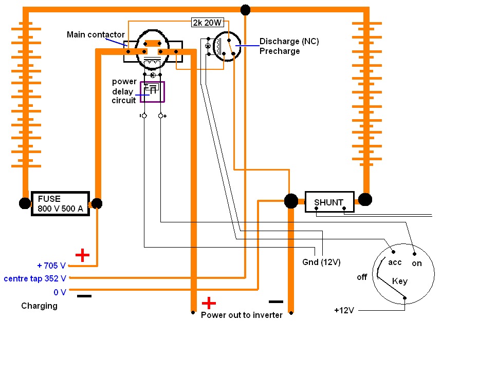
Split pack battery charging
A high voltage battery pack will be utilized in both the eCRX and the electric race bike.
A high voltage battery pack is a critical component in electric vehicles, providing the necessary energy storage to power electric motors effectively. In the...

0-15 Volt Tracking PS
The linear dual tracking power supply, shown in the schematic, provides 0-15 volts, at 1/4 amp, maximum, using a discrete transistor regulator with op-amp feedback to control the output voltage. The supply was constructed in 1975; the negative output voltage...

LM7805 + 5V power supply configuration
The circuit illustrated in the figure provides an output voltage of +5V and an output current of 1.5A. It comprises a power transformer, a bridge rectifier circuit consisting of diodes D1 to D4, and filter capacitor C1. Additionally, capacitors C2...

positive voltage regulator circuit with
The IC8211 serves as a voltage reference and regulator amplifier, with Q1 likely functioning as the series pass transistor. R1 determines the output current of the IC8211, while C1 and C2 contribute to loop stability and help suppress the feedthrough...

Multifunction appliance protection circuit diagram
The circuit consists of a DC voltage regulator, a delay circuit, and protection mechanisms for overvoltage and undervoltage. It utilizes the LM7812 integrated voltage regulator to provide a stable 12V output. The protection circuit samples voltage using R2 and potentiometer...