


10 Amp 13.8 Volt Power Supply circuit
#13.8V
#10A
#current limiting
#surge protection
#regulated
#high current
#voltage regulator
#power electronics
#DIY power supply
#robust

Description: The circuit is designed to deliver a surge current of 12 amps, offering performance that meets or surpasses that of typical commercial units. Additionally, it incorporates a current limiting feature, providing a level of reliability that is superior to many standard commercial systems.
The circuit operates by utilizing a robust power supply capable of handling the specified surge current while maintaining stable performance under varying load conditions. The current limiting feature is achieved through a combination of resistive and active components that monitor the output current. When the current exceeds the predetermined threshold, the circuit automatically reduces the output, preventing potential damage to both the load and the power supply.
Key components of this circuit may include a high-current MOSFET or transistor, which serves as the main switching element, allowing for efficient control of the output current. A current sensing resistor is placed in series with the load to provide real-time feedback on the current flow. This feedback is processed by a control circuit, which could be implemented using an operational amplifier or a dedicated current sensing IC.
The design should also include protective elements such as fuses or circuit breakers to further enhance reliability and safety. Capacitors may be employed for filtering purposes, smoothing out voltage spikes and ensuring stable operation during transient conditions.
Overall, this circuit design not only meets the required current specifications but also emphasizes reliability and safety through its advanced current limiting mechanism.The circuit will give us amps (12 amps surge) with performance that equals or exceeds any commercial unit. The circuit even has a current limiting feature which is a more reliable system than most commercial units have..
The circuit operates by utilizing a robust power supply capable of handling the specified surge current while maintaining stable performance under varying load conditions. The current limiting feature is achieved through a combination of resistive and active components that monitor the output current. When the current exceeds the predetermined threshold, the circuit automatically reduces the output, preventing potential damage to both the load and the power supply.
Key components of this circuit may include a high-current MOSFET or transistor, which serves as the main switching element, allowing for efficient control of the output current. A current sensing resistor is placed in series with the load to provide real-time feedback on the current flow. This feedback is processed by a control circuit, which could be implemented using an operational amplifier or a dedicated current sensing IC.
The design should also include protective elements such as fuses or circuit breakers to further enhance reliability and safety. Capacitors may be employed for filtering purposes, smoothing out voltage spikes and ensuring stable operation during transient conditions.
Overall, this circuit design not only meets the required current specifications but also emphasizes reliability and safety through its advanced current limiting mechanism.The circuit will give us amps (12 amps surge) with performance that equals or exceeds any commercial unit. The circuit even has a current limiting feature which is a more reliable system than most commercial units have..

8V From 5V Regulator Circuit
If locating an 8-V regulator proves difficult, a 5-V unit can serve as a replacement by connecting the regulator as illustrated here.
In electronic circuits, voltage regulators are essential components that maintain a constant output voltage regardless of variations in input...

pinouts
It is essential to implement current limiting when charging batteries. Open frame linear power supplies can be used for this purpose, with the current limit set to the recommended charging current of the battery. Foldback current limiting is particularly useful...

Easy exchange of magnetic saturation voltage regulator circuit
Easy exchange of magnetic saturation voltage regulator circuit
The magnetic saturation voltage regulator circuit is designed to stabilize output voltage levels by utilizing magnetic saturation principles. This circuit typically employs a magnetic core, which operates in saturation to regulate voltage,...

Temperature compensation of the symmetrical power supply 7812 F007C
The circuit is a temperature-compensated power supply that generates a negative voltage to track positive voltage changes in a symmetrical voltage integrated power supply. It features a three-terminal regulator connected with two identical transistors, leveraging the temperature characteristics of the...

Adjustable Current Limit For Dual Power Supply circuit
This current-limiting circuit, illustrated in this example as part of a small bench power supply, could theoretically be utilized alongside any dual-rail current source. The section of the circuit to the left of the diagram restricts the input current to...
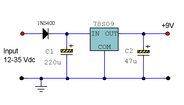
9 Volt 2 Amp Power Supply
This circuit primarily relies on the regulator for its functionality. The 78S09 regulator can provide a continuous output of up to 2 amps while ensuring a low noise and well-regulated supply. Although the circuit can operate without additional components, a...

Simple regulated power supply with overcurrent trip
The 15V zener is fed via the 4.7k resistor from the input. With 0.6V across the base-emitter of the PNP transistor, this establishes a voltage of 14.4V across the 3.3k resistor, so there must be a current of nearly 4.4mA...

12 Volt 30 Amp Power Supply
This power supply utilizes a single 7812 integrated circuit (IC) voltage regulator in conjunction with multiple external pass transistors to provide output load currents of up to 30 amps.
The circuit design incorporates a 7812 voltage regulator, which is known for...

Battery simulator provides current limiting
A constant-voltage active load can function as a battery during the charge cycle. The load voltage can be adjusted from 5 to 35V using potentiometer PV, simulating batteries with voltages ranging from 6 to 32V. In the testing of a...