


12 volt power supply circuit using LTM4096 IC
#LTM4096
#switching regulator
#buckboost
#12 volt
#high efficiency
#fixed output
#power supply circuit
#voltage regulator

Description: A very simple, high-efficiency switching mode buck-boost power supply circuit can be designed using the LTM4609 switching regulator IC. This circuit will provide a fixed output voltage of 12 volts. As illustrated in the schematic, the switching power supply requires few external electronic components. The LTM4609 supports an operating input voltage range of 4.5V to 36V and an output voltage range of 0.8V to 34V, which can be set by a resistor. This high-efficiency design delivers up to 4A current in boost mode operation. The high switching frequency and current mode architecture enable a very fast transient response to line and load changes without sacrificing stability. The LTM4609 can be frequency synchronized with an external clock to reduce undesirable frequency harmonics.
The LTM4609 is a highly integrated buck-boost converter that allows for efficient power conversion across a wide range of input and output voltages. The circuit is designed to maintain a stable output voltage of 12V regardless of variations in input voltage within the specified range. The efficiency of the circuit is enhanced by the use of a current mode control architecture, which provides improved transient response and stability during sudden changes in load conditions.
In the schematic, the LTM4609 is connected to a few essential passive components, including input and output capacitors, an inductor, and a feedback resistor network. The input capacitors are crucial for minimizing voltage ripple and ensuring stable operation, while the output capacitors help maintain the desired output voltage during load transients. The inductor is selected based on the desired current rating and inductance value, which affects the overall efficiency and performance of the converter.
The feedback resistor network is used to set the output voltage to the desired level of 12V. By selecting appropriate resistor values, the output voltage can be accurately adjusted within the range supported by the LTM4609. The device also features a synchronization pin, allowing it to be synchronized with an external clock signal. This capability is particularly useful in applications where multiple converters are used, as it helps to minimize electromagnetic interference (EMI) by reducing the generation of harmonic frequencies.
Overall, the LTM4609-based buck-boost converter is a versatile and efficient solution for applications requiring stable voltage regulation across varying input conditions, making it suitable for a wide range of electronic devices and systems.A very simple high efficiency switching mode buckboost power supply circuit can be designed using the LTM4609 switching regulator IC. This switching power supply circuit will provide an fixed output voltage of 12 volt. As you can see in the schematic circuit, this switching power supply circuit require few external electronic components.
LTM46 09 supports an operating input voltage range of 4. 5V to 36V and supports an output voltage range of 0. 8V to 34V, set by a resistor. This high efficiency design delivers up to 4A current in boost mode operation. The high switching frequency and current mode architecture enable a very fast transient response to line and load changes without sacrificing stability. The LTM4609 can be frequency synchronized with an external clock to reduce undesirable frequency harmonics.
The LTM4609 is a highly integrated buck-boost converter that allows for efficient power conversion across a wide range of input and output voltages. The circuit is designed to maintain a stable output voltage of 12V regardless of variations in input voltage within the specified range. The efficiency of the circuit is enhanced by the use of a current mode control architecture, which provides improved transient response and stability during sudden changes in load conditions.
In the schematic, the LTM4609 is connected to a few essential passive components, including input and output capacitors, an inductor, and a feedback resistor network. The input capacitors are crucial for minimizing voltage ripple and ensuring stable operation, while the output capacitors help maintain the desired output voltage during load transients. The inductor is selected based on the desired current rating and inductance value, which affects the overall efficiency and performance of the converter.
The feedback resistor network is used to set the output voltage to the desired level of 12V. By selecting appropriate resistor values, the output voltage can be accurately adjusted within the range supported by the LTM4609. The device also features a synchronization pin, allowing it to be synchronized with an external clock signal. This capability is particularly useful in applications where multiple converters are used, as it helps to minimize electromagnetic interference (EMI) by reducing the generation of harmonic frequencies.
Overall, the LTM4609-based buck-boost converter is a versatile and efficient solution for applications requiring stable voltage regulation across varying input conditions, making it suitable for a wide range of electronic devices and systems.A very simple high efficiency switching mode buckboost power supply circuit can be designed using the LTM4609 switching regulator IC. This switching power supply circuit will provide an fixed output voltage of 12 volt. As you can see in the schematic circuit, this switching power supply circuit require few external electronic components.
LTM46 09 supports an operating input voltage range of 4. 5V to 36V and supports an output voltage range of 0. 8V to 34V, set by a resistor. This high efficiency design delivers up to 4A current in boost mode operation. The high switching frequency and current mode architecture enable a very fast transient response to line and load changes without sacrificing stability. The LTM4609 can be frequency synchronized with an external clock to reduce undesirable frequency harmonics.

Stable Filament Power Supply Circuit
The circuit diagram illustrates a voltage regulator designed from discrete components to meet specific voltage requirements. It provides two sets of component values for output voltages of 6.3 V (upper) and 12.6 V (lower). The components used include BC547 and...

90Vrms voltage regulator
The circuit is an open-loop RMS voltage regulator designed to deliver 500 watts of power at 90 V RMS, maintaining good regulation within an input voltage range of 110-130 V RMS. When the input voltage is applied, capacitor C1 charges...

Regulator Circuit
The unique feature of this regulator is that the output voltage can be adjusted down to 0 V. The regulation is provided by an integrated regulator type LM317. Typically, in supplies that can be adjusted to 0 V, this IC...

Switching Voltage Regulators-Step up Step down and polarity invert
Switching voltage regulators include step-up, step-down, and polarity-inverting configurations, along with their working principles and circuit diagrams.
Switching voltage regulators are essential components in modern electronic circuits, providing efficient voltage conversion. These regulators can be categorized into three main types: step-up...
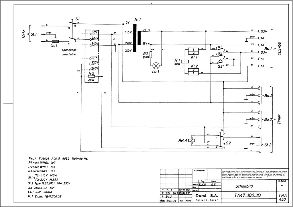
Durst power supplies EST 301 and EST 450
The regulator board of the ES301 has been inspected, revealing that the PCB contacts of the current sensing resistors R42 and R43 are severely burned. There is a nearby group of resistors that also need to be replaced, but their...

1.3V Power supply
This 1.3V power supply can serve as a replacement for the 1.3V Mercury Cell in any circuit. When a 5V input is applied to the circuit, the voltage drop across the Zener diode D1 will be approximately 2V. The diode...

schematics Buck switching regulator based on ATtiny84a -- please critique!
The microcontroller will not be able to drive the gate of Q1 effectively, as GPIO pins typically can only source a few milliamps, resulting in slow turn-on and turn-off times. This limitation will affect the performance of the high-side switch....

DC Power Supply 9 volt using TIP31 transistor
This is a DC power supply circuit designed to regulate 9 volts and provide a current output ranging from 1 amp to 2 amps. The circuit utilizes a modified TIP31 transistor, although alternative transistors such as TIP41, MJE3055, or 2SC1061...

Positive-regulator-with-pnp-boost
The IC8211 serves as the voltage reference and regulator amplifier, with Q1 functioning as the series pass transistor. Resistor R1 defines the output current of the IC8211, while capacitors C1 and C2 ensure loop stability and help suppress the feedthrough...