


15 ampere adjustable power supply
#adjustable power supply
#LM317
#power transistors
#heatsink
#voltage regulation
#high current
#DC power supply
#parallel transistors
#15 ampere
#electronic circuit
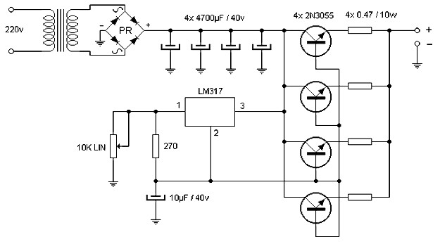
Description: The wiring diagram illustrates that the source delivers a comparable amount of current through the parallel operation of four power transistors, which must be mounted on an effective heatsink. Voltage adjustment is achieved using an integrated LM317, which also requires mechanical dissipation. The schematic diagram is derived from a 15 Ampere Adjustable Power Supply circuit.
The described circuit is a 15 Ampere Adjustable Power Supply, designed to provide a stable output voltage while accommodating varying load conditions. The use of four power transistors in parallel is a critical aspect of this design. This configuration allows for increased current handling capability, ensuring that the power supply can deliver up to 15 Amperes. Each transistor must be mounted on a heatsink to effectively dissipate heat generated during operation, preventing thermal runaway and ensuring reliability.
The LM317 voltage regulator is employed for its adjustable output feature, allowing the user to set the desired voltage level. The LM317 requires a minimum input-output voltage differential to function correctly, typically around 3 volts. Therefore, the input voltage supplied to the LM317 must exceed the desired output voltage by this margin. Additionally, proper bypass capacitors must be placed at the input and output of the LM317 to stabilize the voltage and reduce ripple, enhancing the overall performance of the power supply.
The circuit also includes various passive components such as resistors and capacitors, which play essential roles in setting the output voltage and filtering noise. It is crucial to select components rated for the appropriate voltage and current levels to maintain circuit integrity. The layout of the circuit should minimize the length of the connections between components to reduce inductance and improve transient response.
Overall, this adjustable power supply circuit is suitable for various applications requiring a stable and adjustable output voltage, making it valuable for testing and powering electronic devices. Proper thermal management and component selection are essential to ensure the long-term functionality and performance of the power supply.As is shown in the wiring diagram the source provides similar amount of current through the parallel work of four power transistors, which must be mounted on a good heatsink. The voltage adjustment is performed in integrated LM317, which also must be dissipated mechanically. The schematic diagram come from circuit: 15 Ampere Adjustable Power Suppl y power supply. Go to that page to read the explanation about above power supply related circuit diagram.
The described circuit is a 15 Ampere Adjustable Power Supply, designed to provide a stable output voltage while accommodating varying load conditions. The use of four power transistors in parallel is a critical aspect of this design. This configuration allows for increased current handling capability, ensuring that the power supply can deliver up to 15 Amperes. Each transistor must be mounted on a heatsink to effectively dissipate heat generated during operation, preventing thermal runaway and ensuring reliability.
The LM317 voltage regulator is employed for its adjustable output feature, allowing the user to set the desired voltage level. The LM317 requires a minimum input-output voltage differential to function correctly, typically around 3 volts. Therefore, the input voltage supplied to the LM317 must exceed the desired output voltage by this margin. Additionally, proper bypass capacitors must be placed at the input and output of the LM317 to stabilize the voltage and reduce ripple, enhancing the overall performance of the power supply.
The circuit also includes various passive components such as resistors and capacitors, which play essential roles in setting the output voltage and filtering noise. It is crucial to select components rated for the appropriate voltage and current levels to maintain circuit integrity. The layout of the circuit should minimize the length of the connections between components to reduce inductance and improve transient response.
Overall, this adjustable power supply circuit is suitable for various applications requiring a stable and adjustable output voltage, making it valuable for testing and powering electronic devices. Proper thermal management and component selection are essential to ensure the long-term functionality and performance of the power supply.As is shown in the wiring diagram the source provides similar amount of current through the parallel work of four power transistors, which must be mounted on a good heatsink. The voltage adjustment is performed in integrated LM317, which also must be dissipated mechanically. The schematic diagram come from circuit: 15 Ampere Adjustable Power Suppl y power supply. Go to that page to read the explanation about above power supply related circuit diagram.

Adaptive configuration LM317 adjustable power supply
The adaptive adjustable power supply is illustrated in the accompanying figure. The power supply utilizes an LM317 regulator device, and an adaptive switching circuit that automatically adjusts the input voltage based on the output voltage level. This mechanism reduces the...

0-30 VDC Stabilized Power Supply with Current Control 0.002-3 A
The circuit begins with a step-down mains transformer featuring a secondary winding rated at 24 V/3 A, which connects across the input points at pins 1 and 2. The quality of the output supply is directly related to the transformer's...

High Current 13.8V Power Supply
As is commonly the case, this supply was born of necessity. There is absolutely nothing special about the circuit, except that as shown, it is quite capable of up to 20 Amps intermittently or 10A continuous. Simply use a bigger...

Start-and-run-motor-circuit
The timed two-voltage circuit can start and run a small DC motor or solenoid. The input voltage to the LM317 three-terminal regulator ranges from 5 to 40 V, and the output voltage can range from 2 to 36 V. With...

DC Power Supply (5V 10A)
A circuit is being designed for a DC motor utilizing the following components: 1 x 7805 voltage regulator and 2 x 2N2955 transistors, which are to be paralleled to increase current capacity.
The proposed circuit will employ a 7805 voltage regulator...

Variable Voltage and Current Power Supply circuit
An alternative approach to utilizing operational amplifiers (op-amps) for power supply regulation is presented. This method necessitates an additional winding on the power transformer to provide the op-amps with a bipolar voltage of +/- 8 volts. The negative voltage generated...
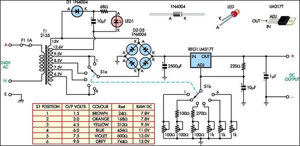
Battery Replacement Power SupplyCircuit Based On The LM317 IC
The following circuit illustrates a Battery Replacement Power Supply Circuit Diagram. This circuit is based on the LM317 integrated circuit. Features include the ability to replace...
The Battery Replacement Power Supply Circuit utilizes the LM317 voltage regulator to provide a stable...

Design and making of the stabilized voltage supply of switch
Under the loading condition of the resistance, the output voltage (Uo) variable range is from 30V to 36V, with a maximum output current (Imax) of 2A. When the input voltage (U2) changes from 15V to 21V, the voltage regulation factor...

Regulator circuit silicon resistor formed
The simple voltage regulator circuit consists of a silicon regulator and a resistor. It is designed to rectify and filter DC voltage, as illustrated in the accompanying figure. The voltage regulator is connected in parallel with the load, and the...