


450W Power Factor Controller with Universal Input Voltage Range
#power factor correction
#universal input
#450W
#AC voltage
#mains supply
#schematic diagram
#high power
#voltage range
#power management
#electrical circuits

Description: This power factor controller accepts voltages ranging from 90 to 268 Vac, which is why it is referred to as a power factor controller with universal input, as it accommodates the mains supply standards in nearly any country. The device is capable of handling loads of up to 450W. The schematic diagram of the power factor controller is provided. It is important to note that the circuit may appear complex; however, much of the schematic represents the internal circuitry of the MC34262 power factor controller integrated circuit chip. The IC can be replaced with the MC33262 to achieve a higher operating ambient temperature range of -40 to 105 degrees Celsius, which is significantly better than the MC34262 chip, which operates within an ambient temperature range of 0 to 85 degrees Celsius.
The power factor controller is designed to improve the efficiency of electrical systems by minimizing the phase difference between voltage and current. This is achieved through the use of a specialized integrated circuit (IC) that regulates the power factor. The MC34262 IC is a key component of this design, providing the necessary control and feedback mechanisms to optimize performance.
The schematic diagram typically includes input voltage connections, output load connections, and various passive components such as resistors, capacitors, and inductors that work in conjunction with the IC to filter and smooth the input waveform. The circuit may also incorporate feedback loops to monitor the output voltage and current, allowing for real-time adjustments to maintain an optimal power factor.
The option to replace the MC34262 with the MC33262 offers flexibility in applications that may require operation in more extreme temperature environments. This adaptability is crucial for installations in regions with high ambient temperatures or in industrial settings where environmental conditions can vary significantly.
Overall, this power factor controller design is suitable for a wide range of applications, including residential, commercial, and industrial settings, where power efficiency is a critical concern. The ability to handle a variety of input voltages and loads makes it a versatile solution for improving energy usage and reducing electricity costs.This power factor controller accept voltage from 90 to 268 Vac, that`s why we call it power factor controller with universal input, since any standards of mains supply in almost any country would fall within that range. This power factor controller is capable of handling up to 450W load. Here is the schematic diagram of the power factor controller circuit: Don`t think this circuit is complex because most of what you see in the schematic diagram is the internal circuitry of MC34262 power factor controller integrated circuit chip. You can replace the IC with MC33262 for higher operating ambient temperature range, -40 to 105 Celsius degree, much better then MC34262 chip that has the ambient operating temperature range of 0-85 Celsius degree.
The power factor controller is designed to improve the efficiency of electrical systems by minimizing the phase difference between voltage and current. This is achieved through the use of a specialized integrated circuit (IC) that regulates the power factor. The MC34262 IC is a key component of this design, providing the necessary control and feedback mechanisms to optimize performance.
The schematic diagram typically includes input voltage connections, output load connections, and various passive components such as resistors, capacitors, and inductors that work in conjunction with the IC to filter and smooth the input waveform. The circuit may also incorporate feedback loops to monitor the output voltage and current, allowing for real-time adjustments to maintain an optimal power factor.
The option to replace the MC34262 with the MC33262 offers flexibility in applications that may require operation in more extreme temperature environments. This adaptability is crucial for installations in regions with high ambient temperatures or in industrial settings where environmental conditions can vary significantly.
Overall, this power factor controller design is suitable for a wide range of applications, including residential, commercial, and industrial settings, where power efficiency is a critical concern. The ability to handle a variety of input voltages and loads makes it a versatile solution for improving energy usage and reducing electricity costs.This power factor controller accept voltage from 90 to 268 Vac, that`s why we call it power factor controller with universal input, since any standards of mains supply in almost any country would fall within that range. This power factor controller is capable of handling up to 450W load. Here is the schematic diagram of the power factor controller circuit: Don`t think this circuit is complex because most of what you see in the schematic diagram is the internal circuitry of MC34262 power factor controller integrated circuit chip. You can replace the IC with MC33262 for higher operating ambient temperature range, -40 to 105 Celsius degree, much better then MC34262 chip that has the ambient operating temperature range of 0-85 Celsius degree.

High power control for sensitive contacts
Two simple arrangements for resistive loads are shown in A and B. The circuit in A will provide load power when the actuating contact is closed, and no power when the contact is open. B provides the reverse of this...

High power transistor amplifier circuits
This circuit is designed for friends who are interested in high-power amplifier circuits. It can deliver approximately 300 Watts RMS and operates as an OCL (Output Capacitor-Less) Class AB amplifier, providing high sound power while systematically protecting the loudspeaker from...

3000 Watt Inverter
This is a high-power inverter circuit designed to deliver an AC power output of 3000W. It converts 12 Volt DC battery voltage into a square wave voltage with a frequency of 50 Hz and a duty cycle of 25%.
The inverter...

Mains Manager
It is common to forget to turn off peripherals such as monitors, scanners, and printers when shutting down a PC. Typically, these devices are connected to a four-way trailing socket, which is plugged into a wall outlet. If this outlet...

2800w high power audio amplifier
The mono high power amplifier is rated at 1400 W. To create a stereo high power amplifier, which would require a total of 2800 W, the necessary components and PCB must be doubled. The schematic circuit diagram provided is incomplete....
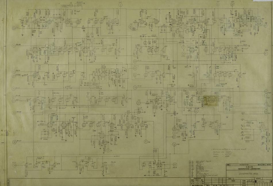
schematic computer arithmetic organ
A schematic diagram illustrates the detailed connections between all components in a circuit. These diagrams are utilized for circuit construction and subsequent testing. In the case of CSIRAC, the primary components included vacuum tubes (valves), capacitors, and resistors. Schematic diagrams...

Active Power Factor Correction Circuit
Active power factor correction stabilizes the electrical demand of a device to provide optimal power factor characteristics for various types of loads. To comply with power factor regulations, a cost-effective solution should be designed. In many applications, the requirement for...

smart amp delay
This system is designed as a Windows service that detects various power events, including Suspend, Hibernate, Reboot, and Shutdown. It can send appropriate responses to a control circuit, specifically a Heartbeat or Kill signal. The trigger mechanism is also regulated...

Power Path Management Battery Charger
Powering the system is required by many applications while charging the battery simultaneously. Interaction between the system and charger may result in a...
Power management in electronic systems is critical, particularly in applications that necessitate simultaneous operation and battery charging. This...