


5V power supply using 7805 IC with circuit diagram
#voltage regulator
#7805 IC
#5V power supply
#circuit diagram
#linear regulator
#DC power supply
#electronic components
#power management
#voltage regulation
#DIY electronics
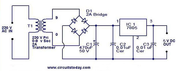
Description: A 5V power supply using IC 7805 is designed and explained with a neat circuit diagram.
The circuit for a 5V power supply utilizing the IC 7805 voltage regulator is a straightforward and efficient design that provides a stable output voltage of 5 volts from a higher input voltage. The IC 7805 is a linear voltage regulator that can handle input voltages ranging from 7V to 35V, making it suitable for various applications where a regulated 5V supply is required.
The basic schematic of the circuit consists of the following components:
1. **Input Capacitor (C1)**: A capacitor, typically in the range of 0.33μF, is connected at the input of the 7805. This capacitor helps to filter out any high-frequency noise from the input voltage source, ensuring a cleaner input signal for the regulator.
2. **Voltage Regulator (IC 7805)**: The central component of the circuit is the 7805 voltage regulator. It has three terminals: the input (Vin), ground (GND), and output (Vout). The input terminal receives the higher voltage, the ground terminal is connected to the circuit ground, and the output terminal provides the regulated 5V output.
3. **Output Capacitor (C2)**: A capacitor, usually around 0.1μF, is connected to the output of the 7805. This capacitor serves to improve the transient response of the regulator and filter any output noise, ensuring that the output voltage remains stable under varying load conditions.
4. **Heat Sink**: Depending on the load current drawn from the regulator, a heat sink may be required to dissipate heat generated by the 7805. The maximum output current for the 7805 is typically 1A, and if the voltage drop across the regulator is significant, the heat generated can exceed safe operating temperatures without a heat sink.
The circuit operates by allowing the input voltage to pass through the 7805, which internally regulates the voltage down to 5V. The output voltage is maintained constant despite variations in the input voltage or the load current, as long as the input voltage remains within the specified range and the load does not exceed the current limit.
This 5V power supply circuit is widely used in various electronic projects, including microcontroller power supplies, sensor circuits, and other applications requiring a stable 5V source. The simplicity of the design, along with the availability of the 7805 component, makes it a popular choice among engineers and hobbyists alike.A 5V power supply using IC 7805 is designed and explained with a neat circuit diagram..
The circuit for a 5V power supply utilizing the IC 7805 voltage regulator is a straightforward and efficient design that provides a stable output voltage of 5 volts from a higher input voltage. The IC 7805 is a linear voltage regulator that can handle input voltages ranging from 7V to 35V, making it suitable for various applications where a regulated 5V supply is required.
The basic schematic of the circuit consists of the following components:
1. **Input Capacitor (C1)**: A capacitor, typically in the range of 0.33μF, is connected at the input of the 7805. This capacitor helps to filter out any high-frequency noise from the input voltage source, ensuring a cleaner input signal for the regulator.
2. **Voltage Regulator (IC 7805)**: The central component of the circuit is the 7805 voltage regulator. It has three terminals: the input (Vin), ground (GND), and output (Vout). The input terminal receives the higher voltage, the ground terminal is connected to the circuit ground, and the output terminal provides the regulated 5V output.
3. **Output Capacitor (C2)**: A capacitor, usually around 0.1μF, is connected to the output of the 7805. This capacitor serves to improve the transient response of the regulator and filter any output noise, ensuring that the output voltage remains stable under varying load conditions.
4. **Heat Sink**: Depending on the load current drawn from the regulator, a heat sink may be required to dissipate heat generated by the 7805. The maximum output current for the 7805 is typically 1A, and if the voltage drop across the regulator is significant, the heat generated can exceed safe operating temperatures without a heat sink.
The circuit operates by allowing the input voltage to pass through the 7805, which internally regulates the voltage down to 5V. The output voltage is maintained constant despite variations in the input voltage or the load current, as long as the input voltage remains within the specified range and the load does not exceed the current limit.
This 5V power supply circuit is widely used in various electronic projects, including microcontroller power supplies, sensor circuits, and other applications requiring a stable 5V source. The simplicity of the design, along with the availability of the 7805 component, makes it a popular choice among engineers and hobbyists alike.A 5V power supply using IC 7805 is designed and explained with a neat circuit diagram..

Design and making of the stabilized voltage supply of switch
Under the loading condition of the resistance, the output voltage (Uo) variable range is from 30V to 36V, with a maximum output current (Imax) of 2A. When the input voltage (U2) changes from 15V to 21V, the voltage regulation factor...

Regulator circuit silicon resistor formed
The simple voltage regulator circuit consists of a silicon regulator and a resistor. It is designed to rectify and filter DC voltage, as illustrated in the accompanying figure. The voltage regulator is connected in parallel with the load, and the...

High Input Voltage Linear Regulator
Commonly used 3-pin linear voltage regulators, such as the LM317, typically cannot handle input voltages exceeding approximately 30V. The LR8A from Supertex Inc is a new adjustable three-pin regulator that can accept input voltages up to 450V and can supply...

Application Circuit CW4960 CW4962 dual voltage + 5V 1.5A -12V 100mA output
The circuit described is a stabilized power supply utilizing the CW4962 and CW4960 components, providing +5V at 1.5A and -12V at 100mA. The +5V output serves as the main power supply. The output circuit employs a transformer rather than an...

12 Volt 30 Amp Power Supply
This power supply utilizes a single 7812 integrated circuit (IC) voltage regulator in conjunction with multiple external pass transistors to provide output load currents of up to 30 amps.
The circuit design incorporates a 7812 voltage regulator, which is known for...

power Voltage supply clipping to <=3.3V
Supply it with a Li-Ion cell, which has a voltage range of 2.7 to 4.2V. The complexity of a buck/boost converter is not desired. While it is possible to regulate the voltage down to anything below 2.5V, it would be...
Regulator circuit silicon resistor formed
The simple voltage regulator circuit consists of a silicon regulator and a resistor. It is designed to rectify and filter DC voltage, as illustrated in the accompanying figure. The voltage regulator is connected in parallel with the load, and the...

DC supply voltage circuit indicates one of the more limited
The circuit for monitoring DC power supply under-voltage and over-voltage is depicted in Figure 13-93. It is designed to ensure that the DC power supply voltage remains within normal operating limits. When the supply voltage is at 12V, the sampling...

Dual Voltage 12V Power Supply
The following circuit diagram of a dual voltage power supply can be used for miscellaneous applications. It requires a few components to build. The most important components of this circuit are regulators: 1: (AN) 7812 and 2: (AN) 7912. AN7812...