


AC input circuit
#AC input
#fuse
#mutual inductance filter
#filter capacitor
#circuit protection
#EMI filtering
#power filtering
#electrical safety

Description: The AC input circuit consists of a fuse (Fl01), a mutual inductance filter (LF101), and filter capacitors (CX101, CY101, CY102), among other components. Its primary function is to filter out noise and pulse interference from the AC circuit, as illustrated in Figure 2-37.
The AC input circuit is a crucial component in power supply designs, ensuring that the incoming AC voltage is clean and stable for subsequent processing. The fuse (Fl01) serves as a protective device that disconnects the circuit in the event of an overcurrent condition, thus preventing damage to downstream components.
The mutual inductance filter (LF101) is designed to reduce high-frequency noise by utilizing the principle of inductive coupling between its coils. This filter is particularly effective in attenuating electromagnetic interference (EMI) that may be present in the AC supply.
The filter capacitors (CX101, CY101, CY102) play a vital role in smoothing out voltage fluctuations and providing a low-impedance path to ground for high-frequency noise. CX101 is typically placed in parallel with the load to bypass high-frequency signals, while CY101 and CY102 are often used for common-mode noise filtering, ensuring that any noise present on the AC line is effectively shunted to ground.
The overall layout of the AC input circuit is designed to minimize inductance and resistance, which helps in maintaining signal integrity and reducing losses. Proper placement of components is essential to ensure optimal performance, with critical attention given to the grounding and shielding of the circuit to further enhance noise immunity.
In conclusion, the AC input circuit is a well-structured assembly of protective and filtering elements that work together to ensure a clean power supply, thereby enhancing the reliability and performance of electronic devices.AC input circuit AC input circuit AC input circuit is a fuse Fl01, mutual inductance filter LF101, filter capacitor CX101, CY101, CY102 and some other structure into its main f unction is to filter the AC circuit noise and pulse interference, as Figure 2-37 shows AC input circuit.
The AC input circuit is a crucial component in power supply designs, ensuring that the incoming AC voltage is clean and stable for subsequent processing. The fuse (Fl01) serves as a protective device that disconnects the circuit in the event of an overcurrent condition, thus preventing damage to downstream components.
The mutual inductance filter (LF101) is designed to reduce high-frequency noise by utilizing the principle of inductive coupling between its coils. This filter is particularly effective in attenuating electromagnetic interference (EMI) that may be present in the AC supply.
The filter capacitors (CX101, CY101, CY102) play a vital role in smoothing out voltage fluctuations and providing a low-impedance path to ground for high-frequency noise. CX101 is typically placed in parallel with the load to bypass high-frequency signals, while CY101 and CY102 are often used for common-mode noise filtering, ensuring that any noise present on the AC line is effectively shunted to ground.
The overall layout of the AC input circuit is designed to minimize inductance and resistance, which helps in maintaining signal integrity and reducing losses. Proper placement of components is essential to ensure optimal performance, with critical attention given to the grounding and shielding of the circuit to further enhance noise immunity.
In conclusion, the AC input circuit is a well-structured assembly of protective and filtering elements that work together to ensure a clean power supply, thereby enhancing the reliability and performance of electronic devices.AC input circuit AC input circuit AC input circuit is a fuse Fl01, mutual inductance filter LF101, filter capacitor CX101, CY101, CY102 and some other structure into its main f unction is to filter the AC circuit noise and pulse interference, as Figure 2-37 shows AC input circuit.
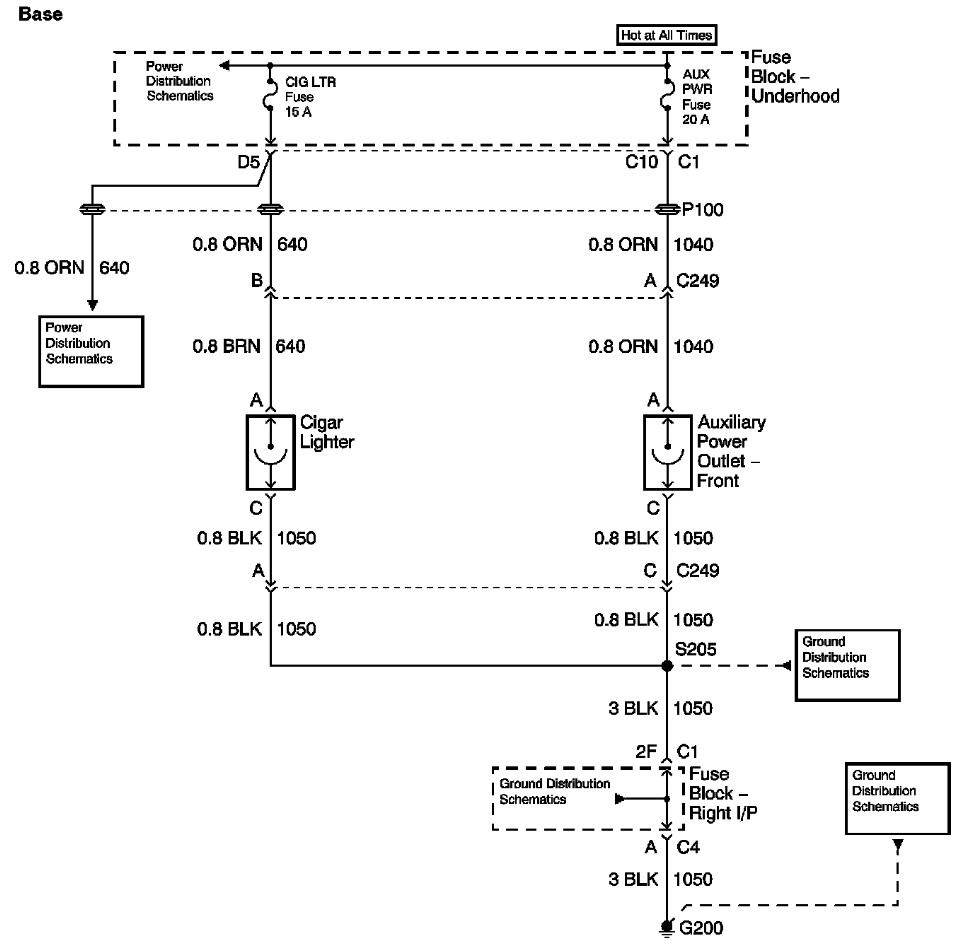
auxillary fuse lighter fuse burned out
The provided information includes a fuse block diagram with the Auxiliary Power (Aux Pwr) fuse highlighted. It is advisable to check both sides of the fuse using a test light or multimeter to ensure functionality. It is assumed that power...

electronic circuit breaker
A circuit breaker is an automatically operated electrical switch designed to protect an electrical circuit from damage caused by overload or short circuit. Its basic function is to detect a fault condition and, by interrupting continuity, immediately discontinue electrical flow....

Fuse with status indicator
The circuit diagram presented illustrates a fuse with an automatic status indicator, designed for operation with a 12V DC supply. While the fuse remains intact, the LED D3 emits a continuous glow; however, if the fuse blows, the LED will...

super psycho
The schematic of the updated power filtering on the R2 PCBs. One of each of the 100n capacitors could be replaced with 10n, or even 220pF to improve the spread of response times to spikes. The Super Psycho Modulation Source...

Fuse Monitor / Alarm
It came to me in a flash. A simple way to see if a fuse has blown without removing it from its holder. Its not often you can design a circuit using just two components, but with just one resistor...

Isolated Fuse Fail Indicator
This circuit utilizes standard components to indicate the fuse status of mains-powered equipment while ensuring electrical isolation from the mains supply. A standard miniature low-power mains transformer (for example, with an output of approximately 6 V at 1.5 VA) serves...
Fuse Monitor / Alarm
It came to me in a flash. A simple way to see if a fuse has blown without removing it from its holder. Its not often you can design a circuit using just two components, but with just one resistor...