


AC power without power transistor switching circuit

Description: An AC-DC power supply without a power switching circuit is typically employed in lighting load circuits. When the power grid is restored, the standby power supply automatically switches on. The automatic switching circuit utilizes a transistor, as illustrated. The automatic switching time is less than 1 second. Figure (a) depicts a direct current (DC) 12V standby power supply; Figure (b) represents a DC 24V standby power supply; and Figure (c) shows an AC backup power supply.
The described AC-DC power supply system is designed to operate efficiently in lighting applications, ensuring seamless transition between the main power source and the standby supply. The absence of a power switching circuit indicates that the system relies on a straightforward design that minimizes complexity and potential points of failure.
The automatic switching mechanism is crucial for maintaining uninterrupted power to lighting loads, particularly in scenarios where power outages are common. The use of a transistor in the switching circuit allows for rapid response times, with the automatic switching time being less than 1 second. This quick response is essential for applications where immediate restoration of lighting is required, such as in emergency lighting systems or critical infrastructure.
The schematic representation includes three figures, each tailored to specific voltage requirements. Figure (a) illustrates a 12V DC standby power supply, which is suitable for low-voltage lighting applications. Figure (b) shows a 24V DC standby power supply, which may be used in systems requiring higher voltage for more extensive lighting setups. Finally, Figure (c) incorporates an AC backup power supply, capable of providing alternating current to lighting loads that are not compatible with direct current.
Overall, this power supply design emphasizes reliability and efficiency, making it appropriate for various lighting applications where maintaining power continuity is essential. The choice of components, particularly the transistor for automatic switching, reflects a careful consideration of performance and operational requirements in real-world scenarios.AC-DC power supply without power switching circuit normally used for lighting load circuit, once the power grid or power is restored, the standby power supply automatic switching immediately. Automatic switching circuit using a transistor as shown, the automatic switching time less than Is. Figure (a) applies to straight stream 12V standby power supply; Fig. (B) for DC 24V standby power supply; FIG. (C) For AC backup power.
The described AC-DC power supply system is designed to operate efficiently in lighting applications, ensuring seamless transition between the main power source and the standby supply. The absence of a power switching circuit indicates that the system relies on a straightforward design that minimizes complexity and potential points of failure.
The automatic switching mechanism is crucial for maintaining uninterrupted power to lighting loads, particularly in scenarios where power outages are common. The use of a transistor in the switching circuit allows for rapid response times, with the automatic switching time being less than 1 second. This quick response is essential for applications where immediate restoration of lighting is required, such as in emergency lighting systems or critical infrastructure.
The schematic representation includes three figures, each tailored to specific voltage requirements. Figure (a) illustrates a 12V DC standby power supply, which is suitable for low-voltage lighting applications. Figure (b) shows a 24V DC standby power supply, which may be used in systems requiring higher voltage for more extensive lighting setups. Finally, Figure (c) incorporates an AC backup power supply, capable of providing alternating current to lighting loads that are not compatible with direct current.
Overall, this power supply design emphasizes reliability and efficiency, making it appropriate for various lighting applications where maintaining power continuity is essential. The choice of components, particularly the transistor for automatic switching, reflects a careful consideration of performance and operational requirements in real-world scenarios.AC-DC power supply without power switching circuit normally used for lighting load circuit, once the power grid or power is restored, the standby power supply automatic switching immediately. Automatic switching circuit using a transistor as shown, the automatic switching time less than Is. Figure (a) applies to straight stream 12V standby power supply; Fig. (B) for DC 24V standby power supply; FIG. (C) For AC backup power.

Class AB Transistor Power Amplifier
Discrete Class AB Transistor Audio Power Amplifier Circuit Diagram. This is a Class AB transistor power amplifier. It is a simple amplifier.
The discrete Class AB transistor audio power amplifier is designed to provide efficient amplification of audio signals while minimizing...

Motor vehicle steering flasher 12
The motor vehicle steering flasher described in the example utilizes high-power transistors as electronic switches, and the circuit is simple and easy to construct. The motor vehicle steering flasher consists of the flash circuit with resistors R1-R3, a capacitor C,...

One Transistor Audio Mixer
The simplest one-transistor audio mixer circuit diagram available. It utilizes a single transistor and can accommodate multiple audio signals, limited only by the user's budget. BC10.
The one-transistor audio mixer circuit is a fundamental design that demonstrates the principles of audio...
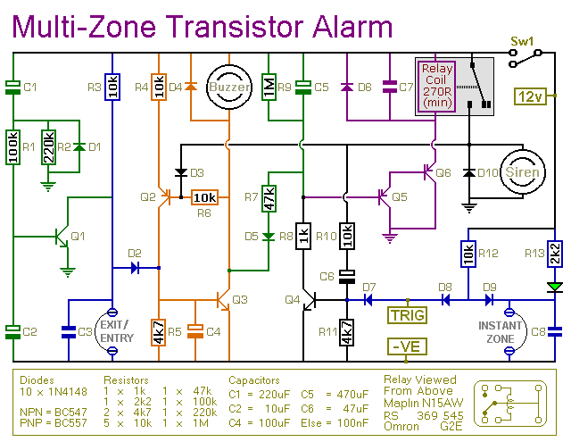
expandable transistor based burglar alarm
This transistor-based alarm system incorporates automatic exit and entry delays, along with a timed bell cut-off and system reset functionality. In addition to the exit/entry zone, the fundamental alarm board includes one instant zone, which is sufficient for many applications....

2 channel audio mixer circuit using transistors
This two-channel audio mixer utilizes 2N3904 transistors to create two preamplifiers. The first preamplifier is designed for high gain, suitable for microphone input, while the second preamplifier allows for control over the audio level input. The audio mixer requires a...

metal detector circuit
This project involves a simple metal detector circuit that is easy to construct using a single transistor and a few additional components. The circuit operates as a Colpitts oscillator, broadcasting on the AM band. To use it, place a quality...

Transistor current mirror circuit
The bases and emitters of the transistors are connected together, resulting in equal base-emitter voltages. Assuming the transistors are identical, equal Vbe leads to equal base currents, which in turn results in equal collector-emitter currents. By adjusting the voltage and...

astable multivibrator transistors
An astable multivibrator, also known as a free-running multivibrator, is a circuit that does not have stable states. Its output oscillates continuously between two unstable states without requiring external triggering. The duration of each state is determined by the resistor-capacitor...

100W full-wave single-junction transistor trigger doer control circuit
A 100W full-wave single-junction transistor trigger control circuit designed for constant or variable speed control of a wire feed motor. The input control signal consists of a voltage adjusted by the master potentiometer (RPs) and a feedback voltage from potentiometer...