


AC welder saving controller circuit diagram
#AC welder
#power saving
#controller
#intermittent load
#energy efficiency
#circuit diagram
#welding equipment
#power consumption

Description: The AC welder operates intermittently, with power consumption during these periods reaching several hundred watts. The AC welder saving controller circuit enables the welding machine to automatically cut off power during no-load conditions while also automatically restoring power for welding, thus achieving energy savings.
The AC welder saving controller circuit is designed to optimize the operation of an AC welder by managing its power consumption effectively. The circuit typically consists of a microcontroller or a relay-based system that monitors the load conditions of the welder. When the welder is not in use—meaning there is no load detected—the circuit will disconnect the power supply, preventing unnecessary energy consumption.
Key components of this circuit may include:
1. **Microcontroller or Relay**: Acts as the central control unit that processes input signals from current sensors and makes decisions to cut off or restore power.
2. **Current Sensor**: This component continuously monitors the current flowing through the welder. If the current falls below a predefined threshold, indicating that the welder is not in use, the sensor sends a signal to the microcontroller to disconnect the power.
3. **Power Relay or Solid-State Relay (SSR)**: This component is responsible for physically disconnecting the power supply to the welder. It is controlled by the microcontroller based on the input from the current sensor.
4. **Power Supply Circuit**: This circuit provides the necessary voltage and current to the control components and ensures stable operation.
5. **User Interface (optional)**: Some designs may incorporate a user interface for settings adjustments, such as threshold levels for load detection or manual override options.
The operational flow begins when the welder is powered on. The current sensor detects the load and sends the information to the microcontroller. If welding activity is detected, the power remains connected. However, once the welding operation ceases, the current sensor identifies the drop in load, prompting the microcontroller to activate the relay and disconnect the power supply.
This automatic power management feature not only enhances the efficiency of the welder but also contributes to energy conservation, reducing operational costs and extending the lifespan of the equipment. The design can be further enhanced with additional features such as indicators for power status or integration with smart home systems for remote monitoring.AC welder is intermittent operation, the intermittent load power consumption during the period up to several hundred watts. AC welder saving controller circuit shown in Fig. Th is circuit allows the welding machine automatically cut off power at no load, but also automatically power welding, thereby saving.
The AC welder saving controller circuit is designed to optimize the operation of an AC welder by managing its power consumption effectively. The circuit typically consists of a microcontroller or a relay-based system that monitors the load conditions of the welder. When the welder is not in use—meaning there is no load detected—the circuit will disconnect the power supply, preventing unnecessary energy consumption.
Key components of this circuit may include:
1. **Microcontroller or Relay**: Acts as the central control unit that processes input signals from current sensors and makes decisions to cut off or restore power.
2. **Current Sensor**: This component continuously monitors the current flowing through the welder. If the current falls below a predefined threshold, indicating that the welder is not in use, the sensor sends a signal to the microcontroller to disconnect the power.
3. **Power Relay or Solid-State Relay (SSR)**: This component is responsible for physically disconnecting the power supply to the welder. It is controlled by the microcontroller based on the input from the current sensor.
4. **Power Supply Circuit**: This circuit provides the necessary voltage and current to the control components and ensures stable operation.
5. **User Interface (optional)**: Some designs may incorporate a user interface for settings adjustments, such as threshold levels for load detection or manual override options.
The operational flow begins when the welder is powered on. The current sensor detects the load and sends the information to the microcontroller. If welding activity is detected, the power remains connected. However, once the welding operation ceases, the current sensor identifies the drop in load, prompting the microcontroller to activate the relay and disconnect the power supply.
This automatic power management feature not only enhances the efficiency of the welder but also contributes to energy conservation, reducing operational costs and extending the lifespan of the equipment. The design can be further enhanced with additional features such as indicators for power status or integration with smart home systems for remote monitoring.AC welder is intermittent operation, the intermittent load power consumption during the period up to several hundred watts. AC welder saving controller circuit shown in Fig. Th is circuit allows the welding machine automatically cut off power at no load, but also automatically power welding, thereby saving.

Reducing the power consumption of the circuit diagram ISO103
This circuit is designed to reduce power consumption in an ISO103 application. It operates with a Vcc1 current of less than 15mA for multi-channel synchronous applications. An oscillator, as illustrated in the figure, can be utilized to generate a TTL...
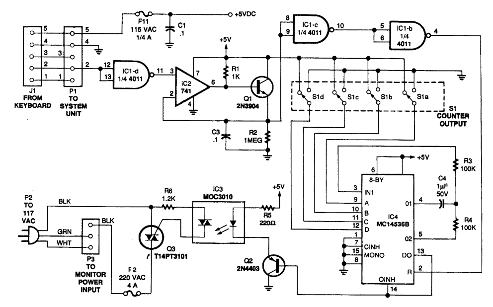
MONITOR POWER SAVER FOR COMPUTERS
The circuit monitors PC keyboard activity through a five-pin DIN connector J1. When a key is pressed, the keyboard transmits a series of negative-going pulses on pin 2. In conjunction with Q1 and C3, the operational amplifier operates as an...

controller
As summer approaches, many individuals focus on staying cool during hot days. For some, this means turning on the air conditioner and enjoying a cold beverage. However, it is essential to consider how to maintain the temperature of radio equipment...

Synchronous controller circuit diagram of a recording transcript
Modern exhibitions utilize extensive sound, light, and electrical technologies for advertising, promotion, and propaganda. This involves various electrical diagrams and control models. Commonly used is an automatic program circuit with pre-recorded commentary, which requires synchronization of two mating times. A...

Simple Power Saving Devices
If a tool is needed to save electricity, a simple power-saving device circuit diagram is suitable for testing. This tool can save electricity in a home by 10-25%. Its operation involves reducing the cosine component of AC current curves, which...

Pulsed Sensor Extends Battery Life
The following demonstrates a power-saving circuit that pulses a sensor for 1 second every 30 minutes. It is designed to monitor the levels of salt. The sensor shown is an optocoupler with an infrared-emitting diode, intended to monitor the level...

Chip carrier test
VA-RICH Power consumption: -2V current draws 34 mA, +2V current draws 5 mA. Total power consumption is 68 mW. Spark protection: Spark protection works, but the spark current burns the trace from pad to input transistor, which makes the channel...
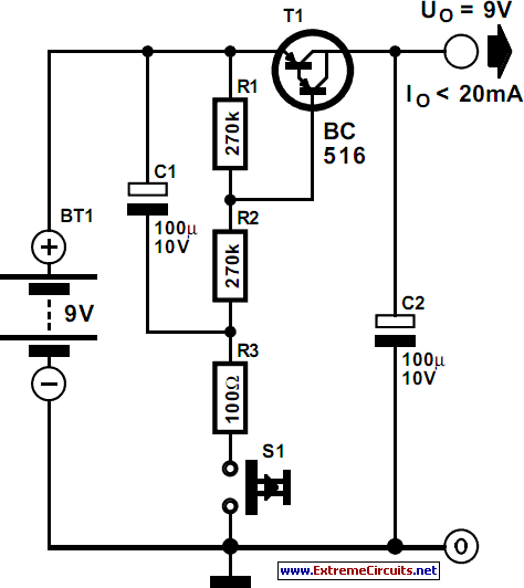
auto power off schematics
Battery-operated devices are increasingly prevalent, and manufacturers strive to minimize current consumption to enable prolonged operation on battery power. However, even minimal current draw can lead to battery depletion if the device is not powered off, resulting in a flat...
MONITOR POWER SAVER FOR COMPUTERS
The circuit monitors PC keyboard activity through a five-pin DIN connector J1. When a key is pressed, the keyboard transmits a series of negative-going pulses on pin 2. In conjunction with Q1 and C3, the operational amplifier operates as an...