


Adjustable DC power supply circuit

Description: An adjustable DC power supply circuit is presented, consisting of a step-down transformer (T), a rectifier bridge (VD1 to VD4), and additional components. The voltage regulator circuit includes an adjustment potentiometer (RP, 5.1 kΩ), allowing the output voltage to vary between 2.5 V and 24 V.
The adjustable DC power supply circuit is designed to provide a stable output voltage that can be tailored to meet specific requirements. The circuit begins with a step-down transformer, which reduces the input AC voltage to a lower AC voltage suitable for rectification. The transformer is selected based on the desired output voltage and current specifications.
Following the transformer, a rectifier bridge composed of four diodes (VD1 to VD4) converts the AC voltage to pulsating DC. The rectifier bridge is configured in a full-wave arrangement, ensuring efficient conversion and minimizing ripple voltage. The output from the rectifier is then smoothed using a capacitor to reduce voltage fluctuations, providing a more stable DC voltage.
The heart of the circuit is the voltage regulator, which maintains the output voltage at the desired level despite variations in input voltage or load current. The adjustment potentiometer (RP, 5.1 kΩ) is connected to the voltage regulator, allowing users to fine-tune the output voltage within a range of 2.5 V to 24 V. This feature is particularly useful for applications requiring different voltage levels, such as powering various electronic devices or experimental setups.
For optimal performance, careful consideration should be given to the selection of components, including the transformer rating, diode specifications, and capacitor values. Additionally, heat dissipation must be addressed, particularly in the voltage regulator, to prevent thermal shutdown or damage.
Overall, this adjustable DC power supply circuit is a versatile solution for providing variable DC voltages, suitable for a wide range of electronic applications.Adjustable DC power supply circuit Shows an adjustable DC power supply circuit, which is composed of step-down transformer T, rectifier bridge pile (VD1 ~ VD4) and other parts of the voltage regulator circuit, the adjustment potentiometer RP (5.i kfl), the output voltage varies between 2.5-24 V.
The adjustable DC power supply circuit is designed to provide a stable output voltage that can be tailored to meet specific requirements. The circuit begins with a step-down transformer, which reduces the input AC voltage to a lower AC voltage suitable for rectification. The transformer is selected based on the desired output voltage and current specifications.
Following the transformer, a rectifier bridge composed of four diodes (VD1 to VD4) converts the AC voltage to pulsating DC. The rectifier bridge is configured in a full-wave arrangement, ensuring efficient conversion and minimizing ripple voltage. The output from the rectifier is then smoothed using a capacitor to reduce voltage fluctuations, providing a more stable DC voltage.
The heart of the circuit is the voltage regulator, which maintains the output voltage at the desired level despite variations in input voltage or load current. The adjustment potentiometer (RP, 5.1 kΩ) is connected to the voltage regulator, allowing users to fine-tune the output voltage within a range of 2.5 V to 24 V. This feature is particularly useful for applications requiring different voltage levels, such as powering various electronic devices or experimental setups.
For optimal performance, careful consideration should be given to the selection of components, including the transformer rating, diode specifications, and capacitor values. Additionally, heat dissipation must be addressed, particularly in the voltage regulator, to prevent thermal shutdown or damage.
Overall, this adjustable DC power supply circuit is a versatile solution for providing variable DC voltages, suitable for a wide range of electronic applications.Adjustable DC power supply circuit Shows an adjustable DC power supply circuit, which is composed of step-down transformer T, rectifier bridge pile (VD1 ~ VD4) and other parts of the voltage regulator circuit, the adjustment potentiometer RP (5.i kfl), the output voltage varies between 2.5-24 V.
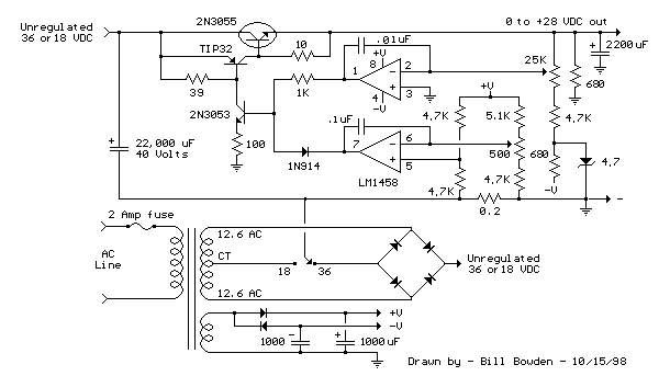
Current and Variable Voltage Power Supply
Another adjustment of application operational amplifiers to adapt a power supply is apparent below. The power supply requires an additional adjustment to supply the op-amps with a bipolar voltage (+/- 8 volts), and the negative voltage is also used to...

Regulator circuit silicon resistor formed
The simple voltage regulator circuit consists of a silicon regulator and a resistor. It is designed to rectify and filter DC voltage, as illustrated in the accompanying figure. The voltage regulator is connected in parallel with the load, and the...

DC supply voltage circuit indicates one of the more limited
The circuit for monitoring DC power supply under-voltage and over-voltage is depicted in Figure 13-93. It is designed to ensure that the DC power supply voltage remains within normal operating limits. When the supply voltage is at 12V, the sampling...
Regulator circuit silicon resistor formed
The simple voltage regulator circuit consists of a silicon regulator and a resistor. It is designed to rectify and filter DC voltage, as illustrated in the accompanying figure. The voltage regulator is connected in parallel with the load, and the...

Adjustable power charger circuit
The charging apparatus depicted in the schematic circuit has a maximum output current of 20A and a maximum charging voltage of 80V. It can be adjusted starting from 0V, making it suitable for charging various types of batteries. The battery...

5G14 3 ~ 6V adjustable power supply
As shown in the figures, this is a practical adjustable power supply. It utilizes an integrated voltage regulator (5G14) in conjunction with a 3DG12A transistor for current spreading, providing an output voltage range of 3 to 6V. The rated output...

Variable charger circuit Schematic Diagram
The accumulator charger circuit must provide a voltage that matches the specifications of the batteries being charged. For a 12-volt accumulator, the output voltage should not exceed 12 volts, nor should it fall significantly below this threshold. Failure to maintain...
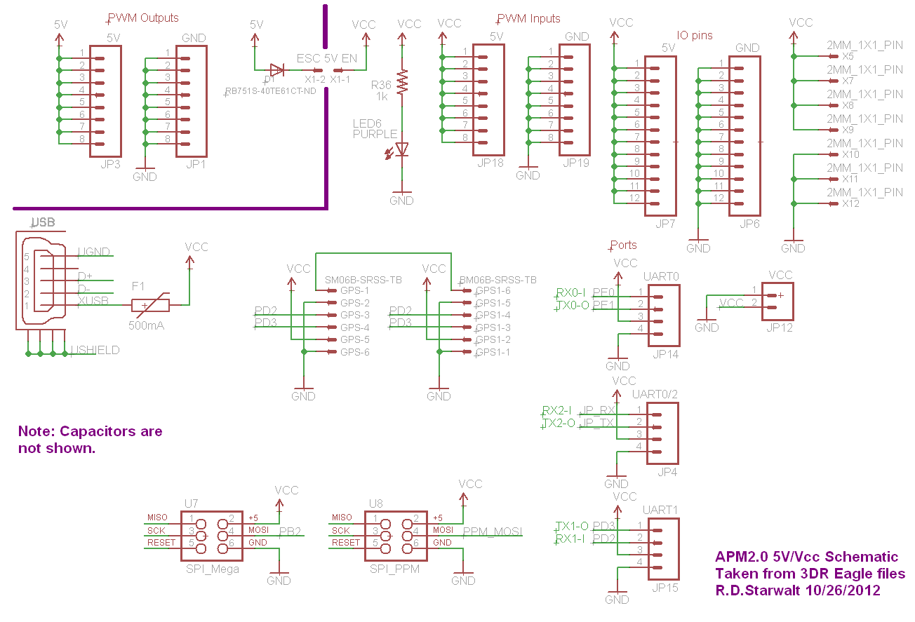
APM2.0 5V/Vcc Schematic
The PWM Output section has been separated into the upper left corner, delineated by a heavy purple line that is bridged by jumper JP1 on the APM2.0. This design choice highlights that diode D1 allows current to pass through JP1,...

psu
The Chameleon II Power Supply Circuits convert the raw input supply into stable voltage outputs necessary for the Chameleon interfaces. The outputs provided are +5V, +12V, and -12V.
The Chameleon II Power Supply Circuits are designed to ensure reliable operation of...