


Automatic UPS system wiring circuit diagram (New Design Very simple) for Home or Office
#UPS
#backup power
#home automation
#office equipment
#battery
#wiring
#emergency power
#energy
#electronics
#circuit design

Description: This wiring circuit diagram is designed for providing power to specific rooms in a home or office during a power supply failure. It ensures continuous power supply to devices such as laptops and computers in those particular rooms, especially when using a low wattage UPS, a single battery, or in the absence of a generator system. To implement this, first remove the live (phase) wires from the main distribution board (circuit breaker) for the rooms intended for automatic supply (from both the battery and main power source without interruption). For instance, if only two rooms are to be connected to this system, the live wires for these rooms should be connected as illustrated. The wiring for the UPS, battery, and home appliances should also follow the diagram. Once completed, power will flow continuously to the designated rooms or office from the main power supply, rather than from the battery, as the battery will only begin charging through the UPS when the main power supply is available.
This circuit design employs a dual-source power supply system, which is essential for maintaining uninterrupted power to critical devices. The circuit is configured to automatically switch between the main power supply and the backup system (UPS or battery) without manual intervention. The inclusion of a UPS is particularly beneficial as it not only provides backup power but also conditions the power supply, protecting sensitive electronics from voltage fluctuations.
The main components of this circuit include a circuit breaker, UPS, battery, and the necessary wiring. The circuit breaker serves as the primary safety device, disconnecting the power supply in case of overload or short circuit conditions. The UPS is connected to the main distribution board, and it should be rated appropriately to handle the combined load of the devices in the connected rooms.
Wiring connections must be executed with care, ensuring that all connections are secure and insulated to prevent short circuits. The live (phase) wires removed from the circuit breaker should be routed to the input of the UPS. The output of the UPS will then be connected to the designated rooms, ensuring that power is supplied seamlessly from the main supply when available.
In cases where the main power supply is interrupted, the UPS will automatically switch to battery power, allowing devices to remain operational without any noticeable interruption. This design is particularly advantageous for environments where continuous power is critical, such as offices with computers and other electronic equipment that cannot afford downtime.
Overall, this circuit design provides a reliable solution for ensuring that essential rooms in a building maintain power continuity, effectively combining both primary and backup power sources in a streamlined manner.This wiring circuit diagram is design for when you want to give supply to particular rooms in the home or office in the building in case of failing the power supply. And you want to supply power continuously to the laptop, computer etc in that specific rooms or office in case of low wattage UPS or single battery or in case of when generator system
is not available. . First of all, remove those Live (Phase) wires from the main distribution board (from the circuit breaker) of those particular Rooms (As shown in Fig) which you want to give automatic supply (in both cases from Battery and Power House without any interrupt or disturbance). Suppose I want to connect only these two rooms with this system as shown in fig. Then connect these two live (phase) wires at the end as shown in fig. Now do the same wiring (Connect UPS, Battery, Home appliances etc) as shown in fig. Done Then power flow will continue to those particular rooms or office at this way from Power supply (Not from Battery, because when power supply available, then battery will start to charge through UPS.
This circuit design employs a dual-source power supply system, which is essential for maintaining uninterrupted power to critical devices. The circuit is configured to automatically switch between the main power supply and the backup system (UPS or battery) without manual intervention. The inclusion of a UPS is particularly beneficial as it not only provides backup power but also conditions the power supply, protecting sensitive electronics from voltage fluctuations.
The main components of this circuit include a circuit breaker, UPS, battery, and the necessary wiring. The circuit breaker serves as the primary safety device, disconnecting the power supply in case of overload or short circuit conditions. The UPS is connected to the main distribution board, and it should be rated appropriately to handle the combined load of the devices in the connected rooms.
Wiring connections must be executed with care, ensuring that all connections are secure and insulated to prevent short circuits. The live (phase) wires removed from the circuit breaker should be routed to the input of the UPS. The output of the UPS will then be connected to the designated rooms, ensuring that power is supplied seamlessly from the main supply when available.
In cases where the main power supply is interrupted, the UPS will automatically switch to battery power, allowing devices to remain operational without any noticeable interruption. This design is particularly advantageous for environments where continuous power is critical, such as offices with computers and other electronic equipment that cannot afford downtime.
Overall, this circuit design provides a reliable solution for ensuring that essential rooms in a building maintain power continuity, effectively combining both primary and backup power sources in a streamlined manner.This wiring circuit diagram is design for when you want to give supply to particular rooms in the home or office in the building in case of failing the power supply. And you want to supply power continuously to the laptop, computer etc in that specific rooms or office in case of low wattage UPS or single battery or in case of when generator system
is not available. . First of all, remove those Live (Phase) wires from the main distribution board (from the circuit breaker) of those particular Rooms (As shown in Fig) which you want to give automatic supply (in both cases from Battery and Power House without any interrupt or disturbance). Suppose I want to connect only these two rooms with this system as shown in fig. Then connect these two live (phase) wires at the end as shown in fig. Now do the same wiring (Connect UPS, Battery, Home appliances etc) as shown in fig. Done Then power flow will continue to those particular rooms or office at this way from Power supply (Not from Battery, because when power supply available, then battery will start to charge through UPS.

1964 xm
I am wiring up my 1964 XM and am unsure where the wires connect for the temperature gauge. On the back of the gauge, there are labels I, S, and A. The wires are colored Green/Black, Red/White, and Yellow/Blue. Do...

Electronics Projects Circuits
Over 1400 top electronics projects and electronic circuits with photos, datasheets, and easy-to-read schematics, along with explanations of how they work and how to build them.
The collection comprises a vast array of electronics projects suitable for enthusiasts and professionals alike....

PowerMan UPS Schematic
PowerMan UPS/Inverters manufactures uninterruptible power supplies and voltage regulators. The business was founded in 1993 and was involved in distribution prior to the year 2000.
PowerMan specializes in providing reliable power solutions, including uninterruptible power supplies (UPS) and voltage regulators, which...

1994 Golf GTI wiring
I have purchased and sold 10 MK3 Jettas and 1 MK3 Golf. This is my first time posting on a forum. I paid $400 for a 1994 GTI with the intention of fixing it and reselling it. The car was...

Automatic switch for batteries
Currently, batteries are becoming increasingly powerful, serving as the sole energy source for portable electronic devices. The rapid evolution of battery technology has prompted manufacturers of electronic equipment to strive for reduced power consumption in their products, enabling them to...

Battery-Voltage Measuring Regulator
This circuit enables a microprocessor system to measure its own battery voltage. A Texas Instruments TI43 precision shunt regulator functions as a precise reference and integrator/amplifier, measuring its own supply through voltage-dependent charge and discharge time intervals. It is important...

Bunch connect the compensating type UPS cascade converter in parallel to study
The demand for high-quality electric energy in modern industrial development is increasing, making it essential to provide safe and reliable green power to energy consumers. Uninterruptible Power Supplies (UPS) are crucial for improving electric energy quality and ensuring the normal...
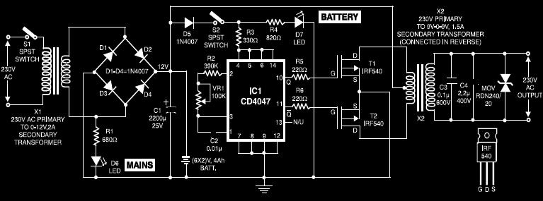
UPS Circuit For Cordless Phones PCB
This circuit diagram of a UPS is designed for use with cordless telephones that cannot operate during a power failure. Since the UPS is intended solely for telephones, its output power is limited to 1.5W. This UPS circuit is economical...

Cordless Phone Backup
Typically, the base of a cordless phone is equipped with an adaptor, while the handset operates using Ni-Cd cells. In the event of a power failure, the base unit becomes inoperative. To address this issue, it is advisable to implement...